
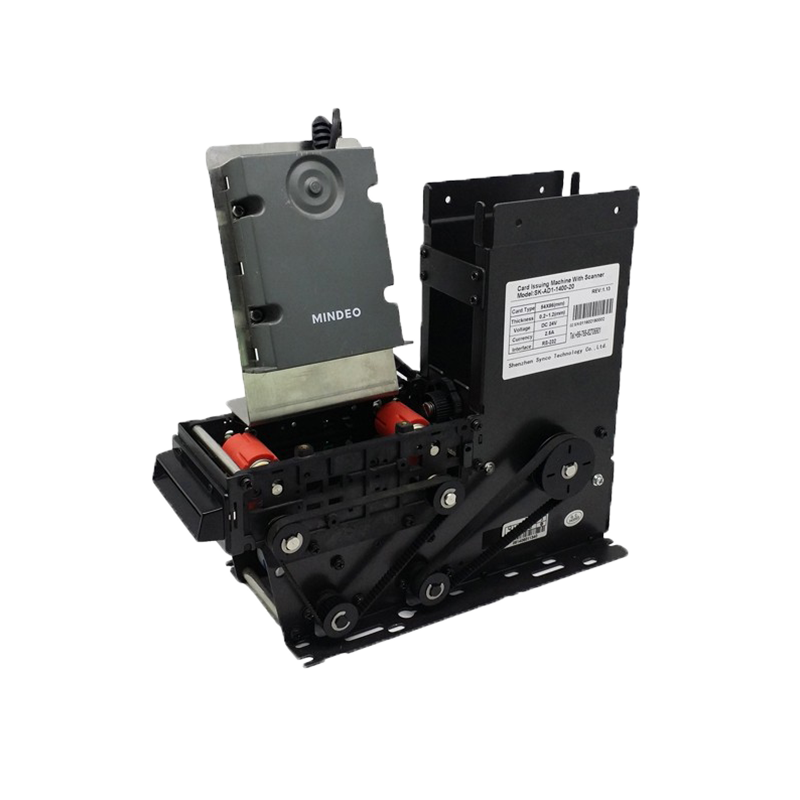
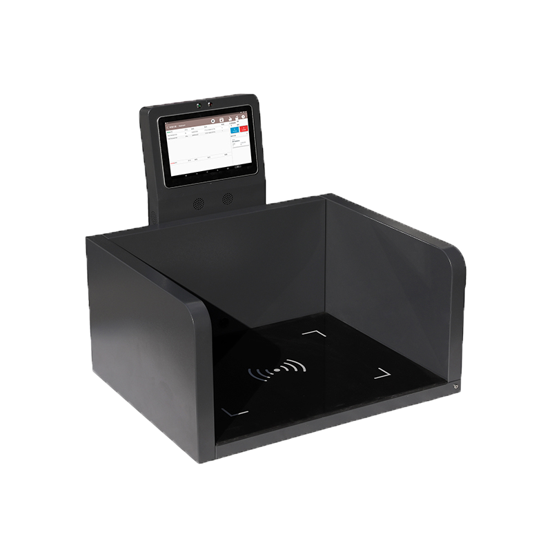
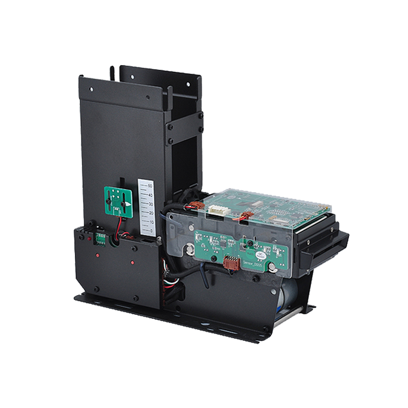

An RFID system is more than an RFID reader and a tag.
A complete industrial RFID deployment may contain:
The exact architecture depends on what the RFID system must accomplish.
A desktop tag-encoding station may contain only a reader, PC, and RFID tag.
A warehouse portal may require:
Tags → Antennas → RF Cables → Fixed Reader → Middleware → WMS
An OEM smart cabinet may instead use:
Tags → Embedded Antennas → UHF Reader Module → Device Controller → Cloud Application
Understanding these components separately makes it much easier to design the complete RFID system correctly.
The most useful way to think about RFID architecture is as five connected layers:
Physical Item & RFID Tag
↓
RF Communication Layer
↓
Reader & Edge Layer
↓
Middleware & Data Layer
↓
Business Application Layer
Each layer has a different role.
The RFID tag identifies the physical object.
The antenna creates the RF interaction zone.
The reader manages communication.
Middleware turns raw tag reads into meaningful events.
The business system decides what those events mean operationally.
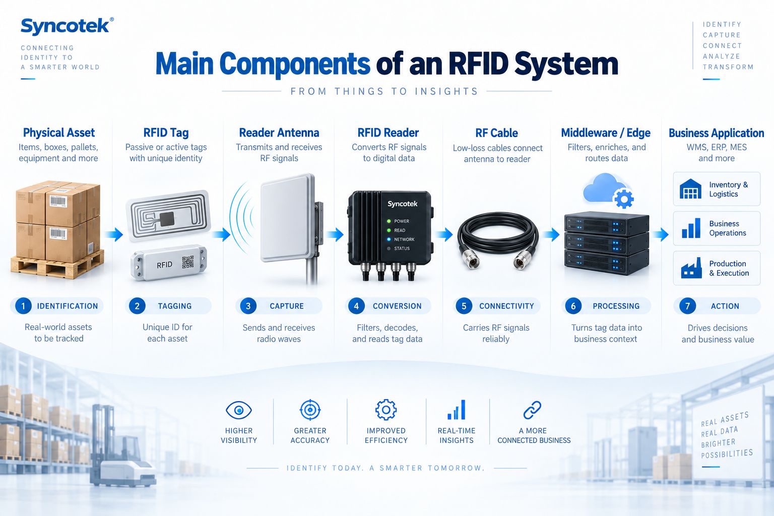
The core components of a typical RFID system are:
| Component | Main Function |
|---|---|
| RFID Tag | Gives the physical item an electronic identity |
| Reader Antenna | Transmits RF energy and receives tag responses |
| RFID Reader | Controls communication with tags and converts RF signals into digital data |
| RF Cable | Connects an external antenna to the reader |
| Middleware / Edge | Filters, enriches, and converts tag reads into usable events |
| Business Application | Uses RFID data in WMS, ERP, MES, inventory, asset, or other systems |
Depending on the architecture, a system may also include:
Not every project needs every component.
For example, an integrated RFID reader may combine the reader electronics and antenna in one enclosure, eliminating the need for separate RF cables.
A handheld RFID reader may combine:
in one device.
System architecture should therefore start with the business workflow rather than a hardware shopping list.
The RFID tag is attached to or embedded in the object being identified.
The object might be:
The tag provides a machine-readable electronic identity.
Depending on the RFID system, this identity may represent:
Passive RFID tags do not require a battery for normal communication.
They receive operating energy from the reader field.
Passive UHF RFID is widely used for:
Advantages include:
Active RFID tags contain a battery.
They can transmit over longer distances and are commonly associated with applications such as:
However, they are normally:
The correct tag technology depends on whether the project needs identification, inventory visibility, or continuous location tracking.
RFID systems can operate in several frequency ranges.
Common categories include:
Passive UHF RFID is especially important in modern supply-chain and inventory applications because it supports relatively long read distances and simultaneous identification of multiple tags.
The same RFID tag can behave very differently depending on what it is attached to.
Important materials include:
Metal can detune ordinary UHF labels.
Water-rich liquids can absorb or alter UHF RF energy.
This is why tags should always be tested on the actual product rather than only in free air.
For more detail, see:
RFID Tag Construction: What Is Inside an RFID Tag?
RFID Inlays, Tags and Labels: What's the Difference?
The RFID reader manages communication between tags and the host system.
In a passive UHF system, the reader typically:
The reader therefore performs both RF and digital-control functions.
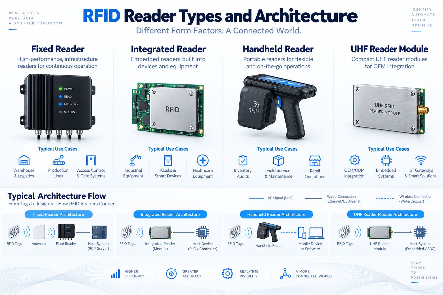
Several reader formats are commonly used.
A fixed reader is installed permanently at a defined location.
Typical applications include:
Fixed readers commonly support multiple external antennas.
For example, a four-port fixed reader can create several read zones using separate antennas.
A fixed reader is usually the best choice where RFID identification should happen automatically without an employee carrying the reader.
An integrated reader combines the RFID reader and antenna into one enclosure.
Typical advantages include:
Integrated readers are useful for:
The tradeoff is reduced flexibility compared with a fixed reader that can support multiple separately positioned antennas.
A handheld reader combines RFID hardware with a mobile computing device.
Typical applications include:
Handheld readers normally include:
They are especially useful where the read zone must move with the operator.
An RFID reader module is a compact board-level or embedded reader designed for OEM integration.
It can be built into:
The module provides the RFID RF and protocol functions while the customer designs:
This is often the most flexible architecture for OEM equipment manufacturers.
Syncotek provides a range of UHF RFID reader modules for embedded RFID integration.
The RFID reader generates the RF signal, but the antenna determines how that energy is delivered into the environment.
Reader antenna selection directly affects:
A well-designed RFID deployment does not aim simply for the greatest possible distance.
It aims to create the correct read zone.
For example:
A warehouse portal should identify pallets passing through the doorway.
It should not continuously read tagged goods stored five meters away.
Antenna gain describes how RF energy is concentrated in a particular direction.
Higher gain can support longer directional coverage but may also create a narrower beam.
Common RFID antenna polarization types include:
Provides strong performance when tag orientation is predictable.
Provides better tolerance when tags may appear in different orientations.
Neither is universally better.
The correct choice depends on how tags move through the read zone.
Beamwidth describes the angular RF coverage.
A narrow beam helps create directional reading.
A wider beam provides broader coverage.
Near-field antennas are useful for:
Far-field antennas are used for:
For more detailed selection guidance, see How to Select the Right RFID Antenna.
These two components are often confused.
| Reader Antenna | Tag Antenna |
|---|---|
| Part of the reader infrastructure | Built into the RFID tag |
| Connected to the reader | Connected to the RFID chip |
| Creates the system read zone | Captures RF energy from the reader |
| May be several centimeters or larger | Often printed or etched into the tag |
| Selected by system integrator | Designed by RFID tag manufacturer |
The reader antenna controls the external RF field.
The tag antenna determines how effectively the tag receives and returns RF energy.
Both must work together.
External RFID antennas are normally connected to a fixed reader through coaxial RF cables.
The cable is not simply a physical connection.
It is part of the RF system.
Every cable introduces signal loss.
Longer cable usually means greater loss.
Additional connectors and adapters can introduce additional losses.
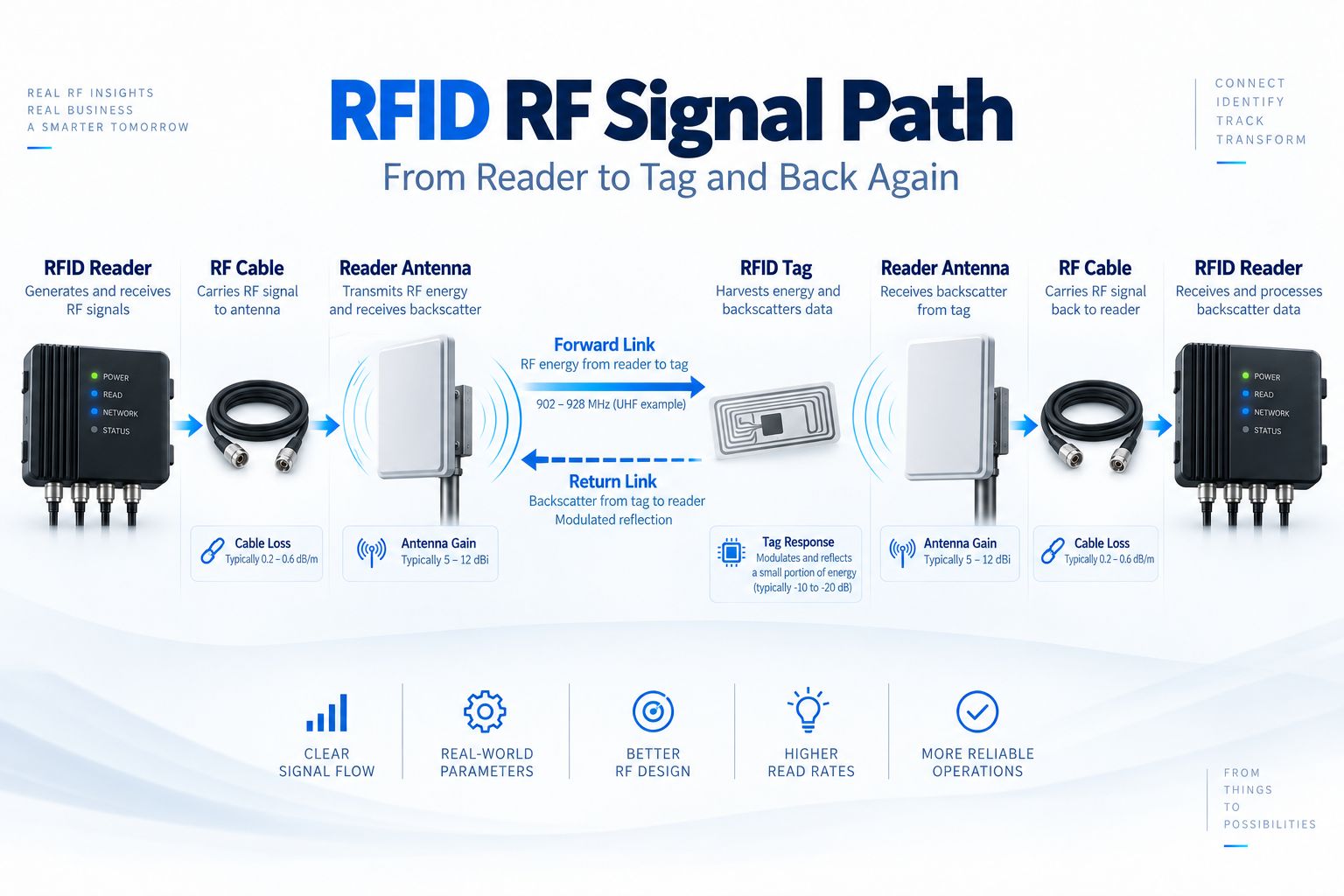
A passive UHF RFID signal travels in two directions.
Reader
→
RF Cable
→
Reader Antenna
→
RF Field
→
RFID Tag
The reader sends RF energy and commands toward the tag.
The tag does not normally generate an independent radio carrier.
Instead it changes how the reader's RF energy is reflected.
The return path is:
Tag Backscatter
→
Reader Antenna
→
RF Cable
→
RFID Reader
The reader then decodes the tag response.
This means cable losses can influence both:
For a deeper explanation of passive UHF communication, see What Is RFID Backscatter?.
For cable selection, see RFID Cables, Connectors and Adapters.
The RFID reader can generate large numbers of raw reads.
The business application normally does not want all of them.
Suppose a pallet stays in front of an RFID antenna for five seconds.
The reader might report the same EPC many times.
The WMS usually does not need:
EPC ABC123 read 47 times.
It needs:
Pallet ABC123 entered Shipping Door 2 at 15:42.
Middleware converts RF activity into business context.
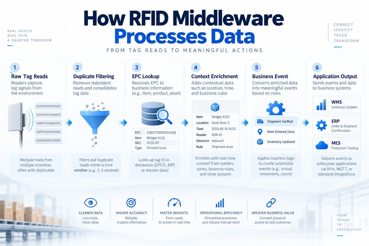
A typical middleware process can include several stages.
Readers send information such as:
Repeated observations of the same tag can be reduced or consolidated.
The RFID identity is mapped to a business object.
For example:
E280...A12B
becomes:
Product: Widget A123
Additional information may be added:
The system creates an event such as:
The resulting event can be sent to:
Middleware is therefore the bridge between the RF world and the business world.
Not necessarily.
A small desktop application may communicate directly with the reader.
Modern readers may also provide:
In these architectures, some traditional middleware functions can run directly on:
The key requirement is not that every project must install a dedicated middleware server.
The requirement is that raw RFID reads must be converted into meaningful and reliable application data.
Traditional architecture often looked like:
Reader → Middleware Server → Enterprise Application
Modern RFID architecture may instead look like:
Reader → Edge Logic → API → Cloud
or:
Reader Module → Device Controller → Business System
Edge processing can perform:
This can reduce:
For industrial RFID systems, edge logic can also interact directly with:
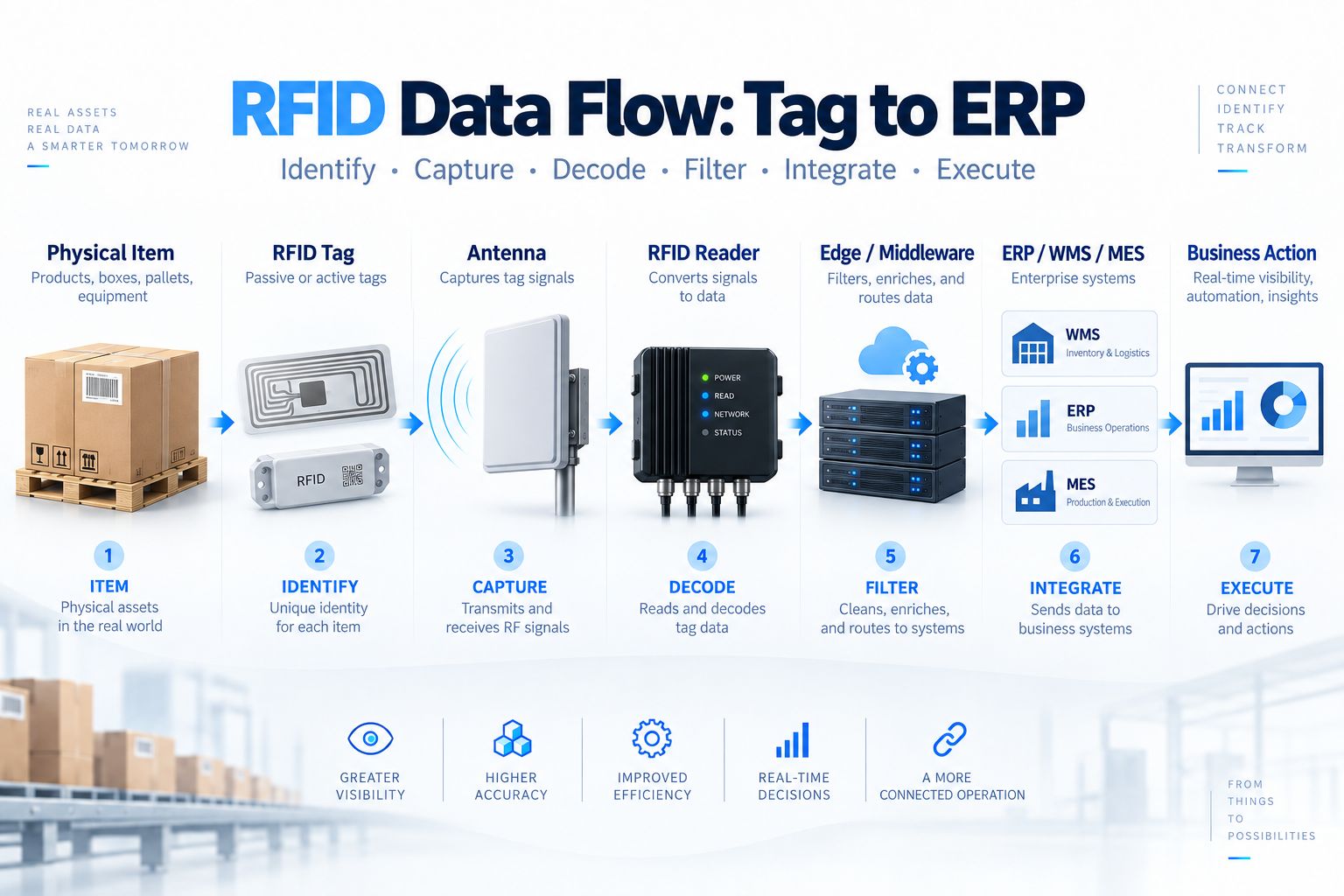
A complete RFID data flow can be represented as:
Physical Item
↓
RFID Tag
↓
Reader Antenna
↓
RFID Reader
↓
Edge / Middleware
↓
ERP / WMS / MES
↓
Business Action
Each stage adds more meaning.
The real-world object exists.
For example:
Pallet of Product A
The tag gives that object an electronic identity.
Example:
EPC 300833B2DDD9014000000123
The reader antenna detects the tag.
The reader converts the backscatter response into digital EPC data.
Middleware determines:
The RFID identity is associated with:
The WMS can then perform an action such as:
Receive pallet into Warehouse A.
or:
Confirm shipment SO-458723.
The value of RFID therefore comes from turning physical identification into operational actions.
An RFID printer encoder is an optional but important component when tags need to be printed and programmed before use.
Typical workflow:
Product Database
↓
Generate EPC
↓
Print Label
↓
Encode RFID Chip
↓
Read Back
↓
Verify
↓
Apply
The printer may produce visible information such as:
while also writing the RFID identity electronically.
RFID printers are commonly used in:
For more detail, see RFID Printers: How to Choose the Right RFID Printer Encoder and How to Program an RFID Tag.
RFID does not need to replace barcode.
Many industrial systems use both.
For example:
Barcode Scan
→ Identify Product SKU
↓
RFID Encode
→ Assign Serialized EPC
↓
Database
→ Link Barcode Product + RFID Item Identity
Barcode can provide:
RFID can add:
The two technologies can complement each other.
A fixed RFID reader often operates as part of a larger automation system.
Additional devices can include:
Consider an RFID shipping portal.
A simple sequence could be:
Photoelectric Sensor Detects Pallet
↓
Trigger RFID Reader
↓
Reader Inventories Tags
↓
Middleware Compares Shipment
↓
Correct
→ Green Light
or
Exception
→ Red Light + Alarm
This architecture prevents the reader from continuously collecting irrelevant tag reads.
Many industrial RFID readers provide General Purpose Input/Output.
Inputs can receive signals from:
Outputs can control:
GPIO allows RFID identification to become part of physical automation.
Readers also need to communicate with host systems.
Common interfaces include:
The correct connection depends on:
Common for fixed industrial readers because it provides:
Useful where network cabling is difficult.
It is common with:
Often used for:
Common for:
Depending on the reader, power may come from:
PoE can simplify fixed installations because network and power are delivered through one Ethernet cable.
Large supply-chain projects may need more than internal inventory records.
They may also need to share standardized visibility events between organizations.
EPCIS is designed for this type of event-data exchange.
A simplified architecture is:
RFID Reader
↓
Raw Observation
↓
Filtering / Event Processing
↓
Business Event
↓
EPCIS Repository
The resulting event can describe:
EPCIS is useful for supply-chain traceability, but it is not necessary for every RFID project.
A small desktop reader or internal inventory system can operate perfectly well without deploying EPCIS.
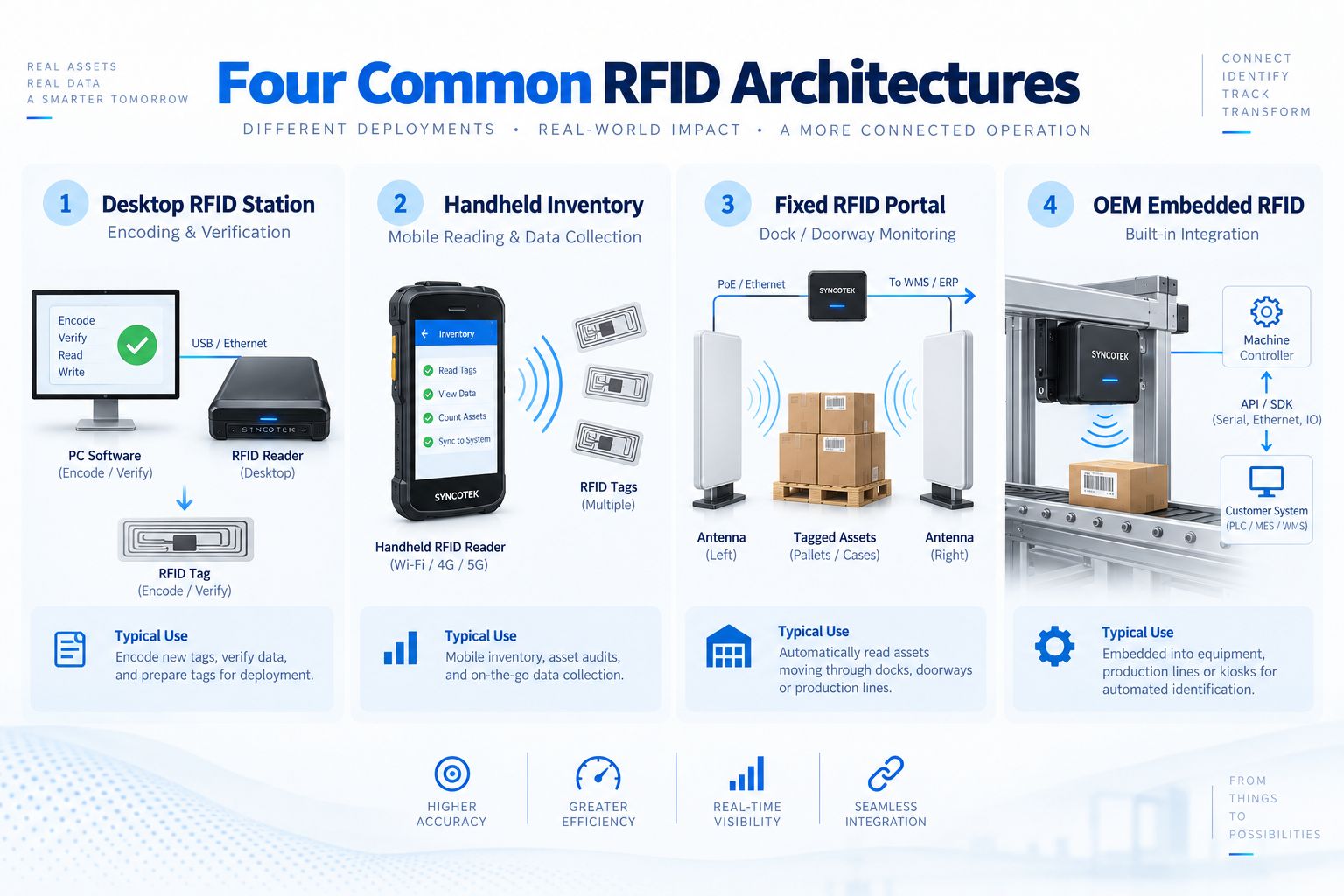
Different applications require different RFID architectures.
Typical components:
RFID Tag
↓
Desktop Reader
↓
PC Software
Applications:
This is the simplest architecture.
For hardware selection, see RFID Reader and Writer.
Architecture:
RFID Tags
↓
Handheld Reader
↓
Wi-Fi / Cellular
↓
Inventory Application
Applications:
The reader and antenna move with the user.
Typical architecture:
Tagged Pallet
↓
Multiple Reader Antennas
↓
Fixed RFID Reader
↓
Middleware
↓
WMS
Applications:
This architecture requires careful control of:
Architecture:
RFID Tag
↓
Embedded Antenna
↓
UHF Reader Module
↓
Host Controller
↓
Customer Application
Applications:
This architecture gives equipment manufacturers maximum control over product design.
A useful starting point is to match reader architecture to the workflow.
| Application | Reader Type | Antenna | Typical Tag |
|---|---|---|---|
| Tag Encoding | Desktop Reader / Printer | Integrated / Near-field | Label / Inlay |
| Mobile Inventory | Handheld | Integrated | UHF Label / Tag |
| Warehouse Portal | Fixed Reader | External Directional Antennas | UHF Tag |
| Smart Cabinet | UHF Module / Fixed Reader | Shelf / Near-field | Item-level Tag |
| Production Line | Fixed Reader / Module | External / Embedded | Industrial Tag |
| OEM Equipment | UHF Module | Custom Antenna | Application-specific Tag |
| Retail Inventory | Handheld / Fixed | Integrated / External | Retail UHF Label |
This table is only a starting point.
The final design must also account for the physical RF environment.
Before choosing hardware, define the following.
How far must the tag be identified?
Do not simply specify:
As far as possible.
Define the real workflow.
Where should the reader detect tags?
Examples:
Will the reader see:
Tag population affects reader configuration and inventory strategy.
Metal and liquids can significantly affect UHF performance.
Will the tag orientation be controlled or random?
This affects antenna polarization.
Moving tags provide less time for reader inventory.
Examples include:
Long RF cables increase system loss.
Place readers strategically rather than automatically using very long cables.
Several readers operating in the same area may create RF interference.
Dense-reader deployments require careful:
For related RF concepts, see What Is Frequency Hopping in RFID?.
UHF RFID regulations differ by region.
Common examples include bands around:
Reader and tag selection must match the deployment region.
Before purchasing hardware, determine how RFID data will reach:
Check required:
Start with the workflow.
Then choose hardware.
More power does not automatically mean a better system.
It can create:
Use enough power to create the required read zone.
A high-performance reader connected through an unnecessarily long, lossy cable can waste RF power.
Always test tags on the real object.
Linear antennas can provide excellent performance when tag orientation is controlled.
Circular polarization may be better when tags rotate.
ERP systems normally need business events, not thousands of duplicate EPC observations.
Use appropriate filtering and event logic.
Some small systems can connect directly to an application.
Do not overengineer.
Inventory identification and continuous real-time location are different requirements.
A portal that reads continuously may capture nearby tags unintentionally.
Physical triggers can make the read event much more reliable.
Reader frequency configuration must match local regulations.
Hardware integration should be planned together with:
A warehouse portal and a smart cabinet solve completely different RF problems.
Architecture must match the use case.
Before deploying an RFID system, confirm:
A typical RFID system includes RFID tags, reader antennas, an RFID reader, middleware or edge software, and a business application. Fixed-reader systems may also require RF cables and connectors.
At the simplest level: RFID tag, reader, and antenna. Practical enterprise systems usually add middleware and business software.
Yes. An RFID reader requires an antenna to transmit and receive RF signals. The antenna may be external or built into the reader.
An integrated reader combines reader electronics and antenna in one enclosure.
An RFID reader module is a compact embedded reader intended for integration into another device such as a smart cabinet, kiosk, printer, or industrial machine.
Middleware filters raw tag reads, removes duplicates, maps EPCs to business objects, adds context, creates events, and passes useful information to enterprise applications.
No. Small systems may communicate directly with the reader, while modern readers or edge devices can perform some middleware functions locally.
The reader antenna is part of the RFID infrastructure and creates the read zone. The tag antenna is built into the RFID tag and receives RF energy from the reader.
Systems using external antennas normally need RF cables. Integrated and handheld readers may not require external RF cables.
Cable loss is the reduction in RF signal strength as energy travels through the coaxial cable between the reader and antenna.
A fixed reader is best for automatic stationary read points. A handheld reader is best for mobile inventory and searching. Neither is universally better.
An RFID portal is a controlled read zone, typically using a fixed reader and multiple antennas, to identify tagged items moving through a doorway or checkpoint.
No. An RFID printer is required only when the project needs to print and encode tags internally.
Yes. Many systems use barcode for visual or point-of-use identification and RFID for automated or bulk identification.
The reader captures the tag identity, middleware or edge software filters and interprets it, and the resulting business event is sent to ERP, WMS, MES, or another application.
EPCIS is a GS1 standard used to capture and share visibility events describing what happened to identified objects in the supply chain.
No. EPCIS is useful for larger supply-chain and data-sharing applications but is not necessary for every RFID deployment.
A typical portal uses UHF RFID tags, fixed reader, two or more external antennas, RF cables, mounting hardware, and often sensors or triggers plus middleware connected to a WMS.
Define the business workflow and required read zone before selecting reader, antenna, tag, and software architecture.
Syncotek provides RFID hardware for system integrators, OEM equipment manufacturers, software companies, industrial automation providers, warehouses, retailers, and asset-management projects.
The Syncotek RFID portfolio includes:
Different applications require different architectures.
A desktop tag-commissioning station should not be designed like a warehouse portal.
A smart cabinet should not use the same RF strategy as a loading dock.
An OEM machine may require an embedded UHF module rather than a finished fixed reader.
Syncotek focuses on the RFID hardware and integration layer, helping customers select reader, module, antenna, tag, and interface configurations for the required application.
Explore the complete Syncotek RFID product range to build an RFID architecture around your actual read zone, product material, operating environment, and software integration requirements.
 Knowledge
Programming an RFID tag means writing useful data into the tag’s memory so that the tag can identify a product, carton, pallet, asset, tool, document, or other tracked item in an RFID system. Many RFID tags are supplied with pre-programmed data, but real projects often require custom encoding. For example, a business may need to […]
READ MORE Knowledge
A successful RFID project should not begin by purchasing readers. It should begin with a business problem. Companies often approach RFID projects with a requirement such as: We want to use RFID in our warehouse. That is not yet an RFID requirement. A much more useful project definition would be: We need to verify whether […]
READ MORE Knowledge
Smart cards are used every day for payments, building access, public transportation, employee identification, hotel rooms, event admission, loyalty programs, and secure authentication. Although they often look like ordinary plastic cards, smart cards contain an integrated circuit that can store, process, or securely exchange digital information. Some smart cards must be inserted into a reader. […]
READ MORE Knowledge
What Is Inductive Coupling in RFID? Inductive coupling is the near-field magnetic coupling method used by most LF RFID and HF RFID/NFC systems. In this architecture, the reader generates an alternating magnetic field with a loop antenna, and a nearby tag with its own loop coil captures energy from that field. The tag then uses that harvested energy to power its […]
READ MORE Knowledge
Manufacturing operations depend on accuracy, timing, and visibility. Materials, tools, fixtures, machines, work orders, semi-finished goods, and finished products move through many production stages every day. When these movements are recorded manually, manufacturers often face delayed updates, inventory errors, missing tools, unclear production status, and limited visibility across the shop floor. RFID technology helps manufacturers […]
READ MOREIf you are interested in our services or need customized solutions, please feel free to contact us.