

Passive UHF RFID tags can communicate without a battery, cellular connection, Wi-Fi radio, or conventional transmitter.
This is possible because the tag does not generate a completely independent radio signal. Instead, it receives energy from an RFID reader, powers its integrated circuit, and changes how much of the reader’s RF energy is reflected back.
This communication method is known as backscatter.
Backscatter is one of the most important concepts in passive UHF RFID. It explains:
A reliable RFID system must complete two separate communication paths:
Understanding both paths helps engineers select tags, antennas, readers, cables, power settings, and installation positions more effectively.
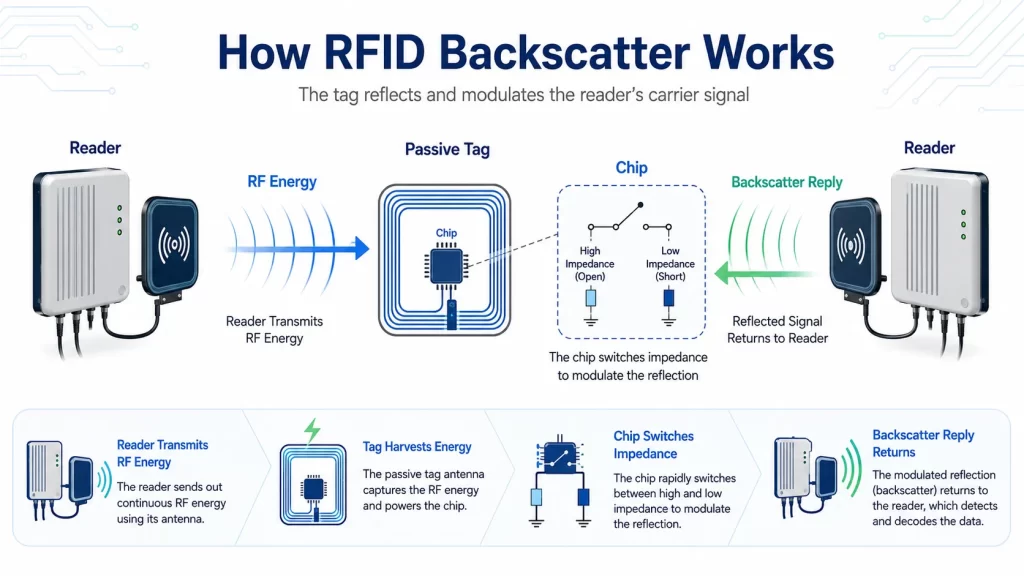
Backscatter communication is a method in which a device communicates by changing the reflection of an existing radio-frequency signal.
In passive UHF RFID, the reader transmits RF energy through its antenna. When an RFID tag enters the RF field, the tag antenna captures part of that energy and supplies it to the tag chip.
After receiving a valid command, the chip switches the electrical load connected to the tag antenna. These changes modify the amount or phase of RF energy reflected from the tag.
The reader detects these controlled reflections and converts them back into digital information.
The tag is therefore not transmitting in the same way as a battery-powered radio. It is modifying and reflecting the reader’s carrier signal. GS1 defines UHF Gen2 as a passive-backscatter, interrogator-talks-first RFID system, meaning the reader initiates communication before a tag responds.
A simple way to understand backscatter is to imagine a flashlight and a mirror.
The flashlight represents the RFID reader. The mirror represents the RFID tag.
The flashlight sends light toward the mirror. The mirror does not create its own light, but it can reflect some of the original light back.
If someone changes the angle or reflective surface of the mirror in a controlled pattern, the reflected light can carry information.
A passive UHF RFID tag works according to a similar principle:
The real RFID process is more advanced because it uses precise impedance changes, digital encoding, modulation, timing, and anti-collision protocols.
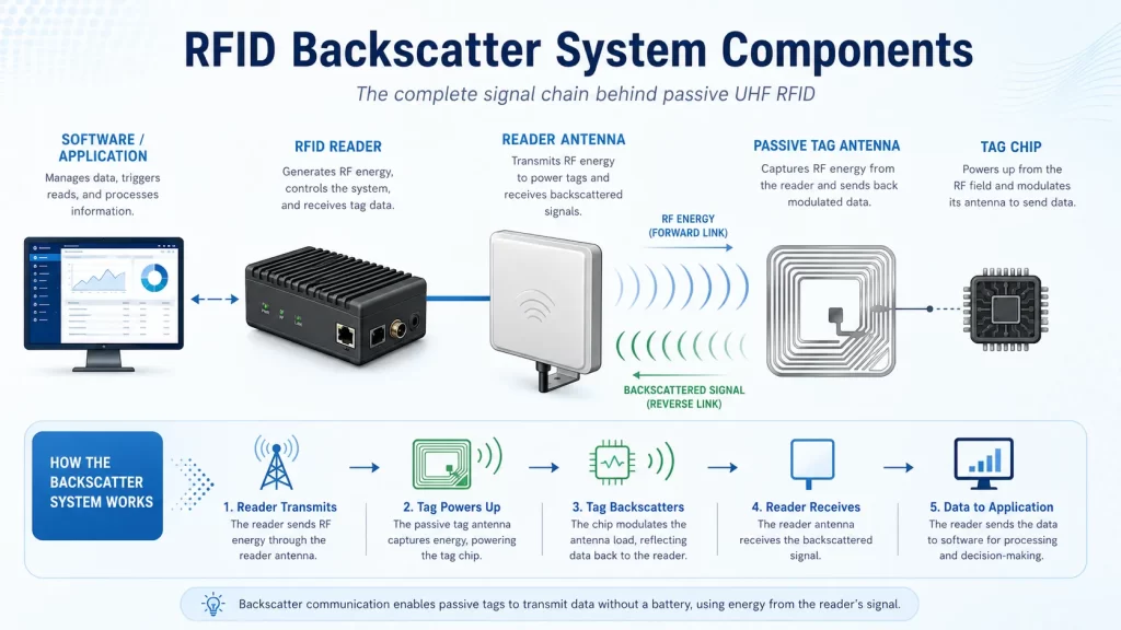
A passive UHF RFID system normally contains the following components.
The RFID reader generates commands and RF energy. It also receives and decodes tag responses.
The reader performs several functions:
Because the reader both transmits a strong signal and listens for a weak response, receiver design and signal isolation are critical.
The reader antenna converts electrical RF power into electromagnetic waves and receives reflected signals from tags.
The antenna influences:
Antenna selection and positioning directly affect both the forward and reverse communication links.
Syncotek’s guide on how to select the right RFID antenna explains antenna gain, polarization, beamwidth, and installation considerations.
The tag antenna captures energy from the reader and returns the modulated backscatter signal.
Tag antenna performance depends on:
The same chip may perform very differently when connected to different tag antenna designs.
The tag chip manages power harvesting, command processing, memory, security functions, and backscatter modulation.
A passive tag chip normally includes:
Modern tag chips are designed to operate with extremely small amounts of received RF power. Improvements in chip sensitivity and backscatter efficiency can allow smaller tags and more reliable reads in difficult environments.
RFID software controls reader settings and transforms raw tag responses into operational information.
It may manage:
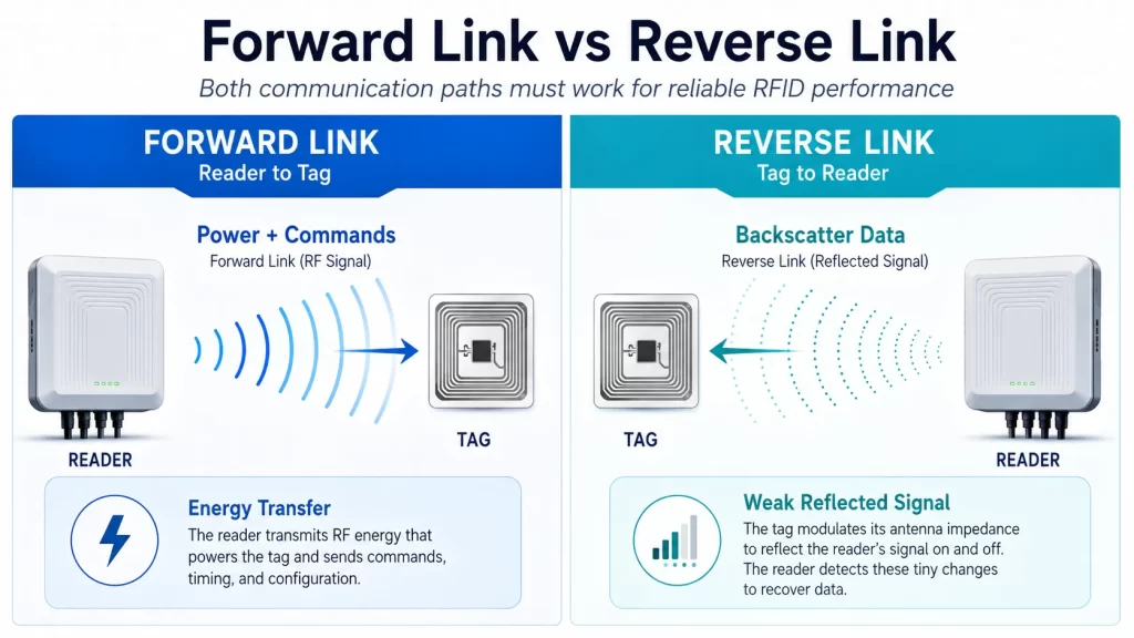
RFID backscatter communication contains two separate links.
The forward link is the communication path from the RFID reader to the tag.
During the forward link, the reader:
The tag must receive enough power to activate its chip and enough signal quality to decode the reader’s command.
The reverse link is the communication path from the RFID tag back to the reader.
During the reverse link, the tag:
The reader must detect this weak signal while managing its own transmitted carrier, environmental reflections, neighboring readers, and electrical noise.
A system can fail at either link.
A tag may receive enough power to activate but return a signal too weak for the reader to decode. Alternatively, the reader may be sensitive enough to detect a reply, but the tag may never receive sufficient energy to power up.
UHF Gen2 RFID is an interrogator-talks-first system.
The interrogator is the RFID reader.
This means a passive RFID tag does not normally transmit whenever it enters a read zone. It waits until it receives RF energy and a valid reader command.
A simplified sequence is:
A tag only backscatters data after being instructed by a compatible reader.
A passive tag does not contain a battery. It must convert part of the reader’s RF signal into usable DC power.
The tag antenna captures alternating RF energy. The chip’s rectifier converts that RF energy into DC voltage.
The energy is then used to operate:
The tag must receive enough energy to cross its operating threshold.
If the available energy falls below that threshold, the chip may:
Tag sensitivity indicates how little RF power a chip or complete tag needs to operate reliably.
Tag sensitivity describes the minimum power required for the tag chip to operate and respond.
A tag with better sensitivity can activate with less received energy.
This can support:
However, chip sensitivity is not the same as complete tag performance.
The final result also depends on:
Impinj notes that a properly tuned tag requires less energy to respond and can provide longer read distance and better reading accuracy.
The tag chip communicates by switching the load connected to the tag antenna.
Different loads create different electrical conditions at the antenna terminals. These conditions change how the incoming RF energy is absorbed or reflected.
The tag rapidly switches between selected impedance states according to the data it needs to transmit.
This creates controlled changes in:
The reader receives these changes and interprets them as encoded digital data.
NXP describes passive UHF tag operation as demodulating data sent by the interrogator and modulating the interrogator’s electromagnetic field to return data from the tag to the reader.
The reflection coefficient describes how much of an incoming signal is reflected by an electrical load and how the phase of that reflection changes.
In an RFID tag, the chip changes the electrical load presented to the antenna.
One state may absorb more power and reflect less. Another state may reflect more power or shift the phase of the reflected carrier.
By switching between these states, the chip creates a modulated backscatter signal.
This is similar to changing the reflective condition of the mirror in the earlier analogy, but it happens electronically and extremely quickly.
The reader communicates commands to the tag by modulating the carrier.
UHF Gen2 readers may use modulation methods including:
ASK means Amplitude Shift Keying. Information is represented through controlled changes in carrier amplitude.
Double Sideband Amplitude Shift Keying changes the carrier amplitude and produces spectral components on both sides of the carrier.
Single Sideband Amplitude Shift Keying reduces one sideband and can reduce occupied spectrum.
Phase-Reversal Amplitude Shift Keying combines amplitude changes with phase reversal characteristics.
The exact modulation modes supported depend on the reader, RF mode, regional requirements, and Gen2 implementation. GS1 conformance documents identify DSB-ASK, SSB-ASK, and PR-ASK among supported reader modulation types.
Reader-to-tag commands commonly use Pulse-Interval Encoding, or PIE.
PIE represents digital data through differences in pulse timing rather than simply turning the carrier completely off for long periods.
This is important because the tag needs continuous or near-continuous RF energy to remain powered while receiving commands.
A long loss of reader energy could cause the passive tag to reset before the command is completed.
During the reverse link, the tag communicates by modulating the backscattered carrier.
Tag modulation may use amplitude-based or phase-based changes, depending on the tag and standard implementation.
GS1 Gen2 supports backscatter data coding based on:
The reader selects the backscatter parameters that tags use for the response.
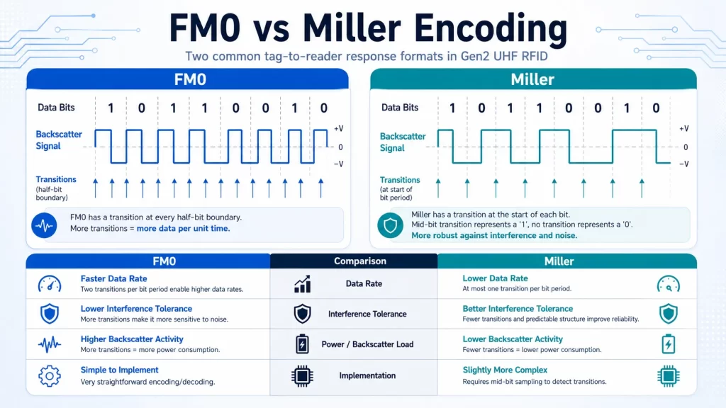
FM0 is a baseband encoding method used for tag-to-reader communication.
FM0 generally supports:
However, faster modes may be more sensitive to noise and reader interference.
Miller encoding uses a subcarrier and can provide stronger spectral separation between the reader carrier and tag response.
It may support better performance in:
The tradeoff is usually a lower tag data rate than the fastest FM0 configurations.
Reader modes balance read speed, receive sensitivity, and resistance to interference by changing air-interface parameters and modulation settings.
A passive RFID tag returns only a small fraction of the energy transmitted by the reader.
The reverse signal is weak because:
The reader must separate the useful tag response from:
This is why a reader’s receive sensitivity and interference rejection are critical.
A link budget accounts for the gains and losses across the complete RFID communication path.
Important forward-link factors include:
Important reverse-link factors include:
The RFID system relies on both power transfer and information exchange. As tag power sensitivity improves, reverse-link detection can increasingly become the limiting factor in some applications.
RFID backscatter uses a two-way radio path.
The reader signal travels:
Both paths experience propagation loss.
In a simplified free-space model, the round-trip signal can decrease much more rapidly with distance than a conventional one-way radio link.
This means a relatively small increase in distance can create a significant reduction in the returned signal.
Increasing reader power alone may not solve the problem if:
Transmit power and receive sensitivity perform different roles.
Transmit power affects how much RF energy is delivered toward the tag.
Higher power can help:
However, excessive power can create:
Receive sensitivity describes how weak a tag response the reader can detect and decode.
Better receive sensitivity can help detect:
Transmit power cannot compensate fully for poor receiver performance.
A balanced RFID system requires sufficient forward-link power and reverse-link sensitivity.
Backscatter systems can be organized in different architectures.
In a monostatic system, the carrier transmitter and backscatter receiver are located in the same reader system.
Commercial fixed and handheld UHF RFID readers commonly use this architecture.
Advantages include:
A major challenge is separating the weak tag response from the reader’s own strong carrier.
In a bistatic system, the RF carrier source and backscatter receiver are physically separated.
Potential advantages include:
However, bistatic systems require more complex coordination and are less common in standard commercial inventory deployments. Academic literature distinguishes monostatic systems, where the emitter and receiver are colocated, from bistatic systems with separated components.
Backscatter is strongly associated with far-field UHF RFID, but RFID technologies do not all use the same coupling method.
LF and HF systems typically operate through near-field magnetic or inductive coupling.
The reader creates a magnetic field, and the tag interacts with that field through a coil antenna.
The tag may communicate using load modulation, changing the electrical load on its coil to create detectable variations at the reader.
UHF RFID typically operates through far-field electromagnetic propagation and backscatter modulation.
This supports:
The difference is important when selecting readers, antennas, cards, and tags. An HF/NFC reader cannot communicate with a UHF Gen2 tag simply because both are described as RFID.
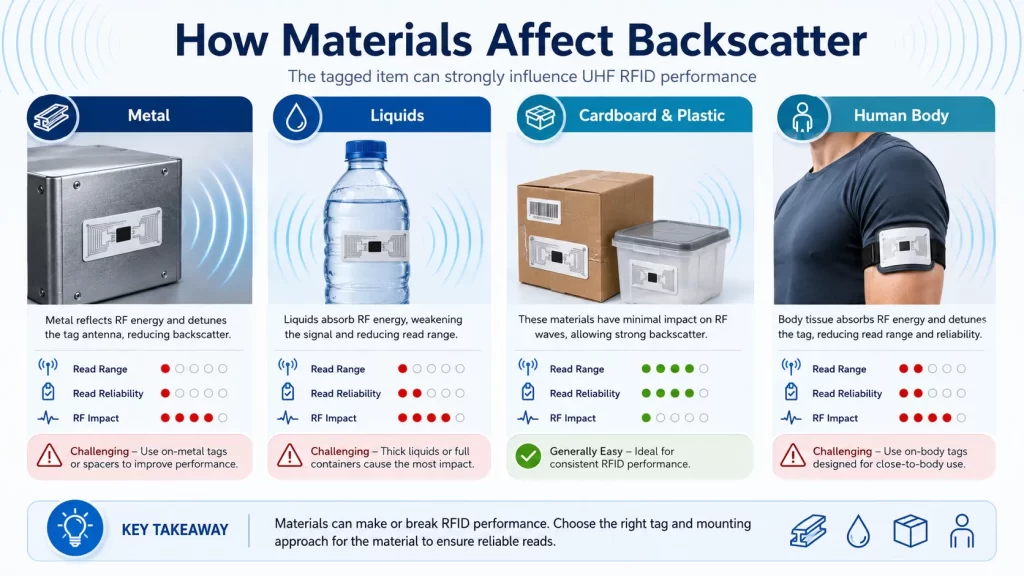
The item behind or around the RFID tag can change antenna tuning and backscatter performance.
Metal is conductive and strongly affects the electric field around a UHF tag.
Directly attaching a standard RFID label to metal can:
Metal assets normally require specialized mount-on-metal RFID tags or carefully designed spacers and mounting structures.
Water-rich liquids absorb and alter UHF RF energy.
Products containing water may:
Applications involving beverages, chemicals, food, pharmaceuticals, or the human body require testing on the actual item.
These materials are generally easier for UHF RFID than metal or high-water-content products, but thickness, density, adhesives, coatings, and nearby objects can still affect performance.
The human body contains significant water and can absorb UHF RF energy.
Badges, wearable tags, wristbands, and attendee credentials should be designed and positioned for on-body performance.
Reader antennas and tag antennas have polarization characteristics.
A linearly polarized reader antenna provides strong performance when the tag is aligned correctly, but performance may fall when the tag rotates.
Circularly polarized antennas can support more variable tag orientations but may provide lower peak gain than an equivalent linear antenna.
Orientation affects:
Tag orientation should be tested through the full range of positions expected in the real workflow.
RF signals can reflect from:
The direct signal and reflected signals may combine constructively or destructively.
Constructive interference can strengthen the field.
Destructive interference can create weak spots or nulls where a tag is difficult to read.
Multipath can cause a tag to read successfully at one location but fail after moving only a small distance.
Potential controls include:
UHF RFID readers may operate across multiple permitted channels.
When the reader changes frequency, the RF environment and tag antenna response may also change.
A tag may perform differently from one channel to another because of:
Frequency hopping can create channel diversity, but it does not replace proper tag and antenna design.
Syncotek’s article on frequency hopping in RFID explains channel changes, reader interference, regional rules, and Dense Reader Mode.
RFID reader modes control communication parameters such as:
A faster mode may provide more tag reads per second but lower tolerance to interference.
A dense-reader mode may improve coexistence but reduce maximum inventory speed.
The correct mode depends on:
Tag activation and successful decoding are separate events.
A tag may receive enough energy to turn on but still fail because:
This is why testing only the tag’s maximum activation range does not fully evaluate RFID performance.
A reliable test should measure repeatable tag reads under realistic conditions.
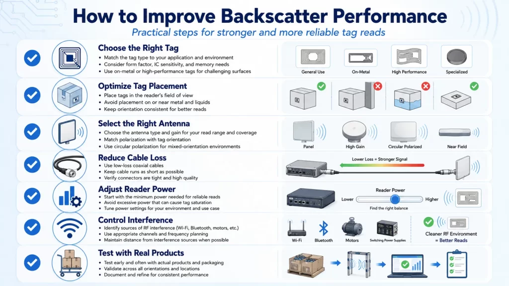
The tag must be tested on the actual product or asset.
Consider:
For a broader overview of tag construction, see Syncotek’s guide to RFID inlays, tags, and labels.
Moving a tag by a few centimeters can significantly affect performance.
Test several positions and evaluate:
Select antenna gain and polarization according to the required read zone.
The antenna should concentrate energy in the intended area without creating excessive stray reads.
RF cables reduce both transmitted power and received backscatter signal.
Long or low-quality cables can weaken both communication paths.
Use suitable RFID cables, connectors, and adapters and minimize unnecessary cable length.
Use enough power to activate tags reliably, but avoid automatically using the maximum setting.
Measure performance at several power levels to identify the lowest reliable value.
Use faster modes for high-speed, controlled environments and interference-resistant modes for dense-reader installations.
Review:
Good read-zone design may include:
A single tag in an empty room does not represent a real deployment.
Test with:
Passive tags do not contain a conventional powered transmitter, but they do communicate by modulating and reflecting the reader’s RF carrier.
Higher power may activate more tags, but it can also create stray reads and interference. It may not solve a weak reverse link.
Read range depends on the complete system:
Different chips, antennas, materials, sizes, and designs provide different sensitivity and backscatter efficiency.
Attaching the tag to metal, liquid-filled products, electronics, or the human body can significantly change performance.
Backscatter is the method used by the tag to return data.
Frequency hopping is the reader’s movement between permitted RF channels.
Improved tag sensitivity means some modern deployments may become reverse-link limited, where the tag activates but the reader cannot reliably detect the returned signal.
Before finalizing an RFID deployment, confirm:
RFID backscatter is the communication method that allows passive UHF RFID tags to return information without using a battery-powered transmitter.
The reader supplies RF energy and sends commands through the forward link. The tag harvests that energy, processes the command, and switches its antenna impedance to create a modulated reflection. The reader detects and decodes that weak reflected signal through the reverse link.
Reliable backscatter communication depends on the complete RFID system:
For successful deployment, engineers should not evaluate only whether a tag can be read once.
The goal should be reliable, repeatable communication across the complete operating workflow.
RFID backscatter is a communication method in which a passive tag changes how it reflects the RFID reader’s RF carrier to return encoded data.
The tag captures energy from the reader’s RF field, converts it into electrical power, activates its chip, and uses controlled reflection changes to return data.
The forward link is the communication path from the RFID reader to the tag. It provides energy, commands, and operating parameters.
The reverse link is the tag-to-reader communication path. The tag returns data by modulating the reflected reader carrier.
A passive UHF tag does not generate a conventional independent carrier. It modulates and reflects the carrier supplied by the reader.
Backscatter modulation is the controlled switching of the tag antenna’s electrical load to change the amplitude or phase of the reflected signal.
UHF RFID generally uses far-field backscatter. LF, HF, and NFC systems generally use near-field inductive coupling and load modulation.
Only part of the reader’s transmitted energy reaches the tag, and only part of that energy is reflected back. The returned signal also experiences propagation loss and environmental interference.
The tag may receive enough energy to activate, but its returned signal may be too weak or distorted for the reader to decode.
It can improve tag activation, but it does not automatically improve reader receive sensitivity or solve tag detuning, interference, orientation, or cable-loss problems.
Important factors include reader power, reader sensitivity, antenna gain, cable loss, tag sensitivity, tag antenna design, orientation, product material, frequency, multipath, and interference.
FM0 and Miller are Gen2 tag-to-reader encoding methods. FM0 can support faster data rates, while Miller can provide stronger interference tolerance in some environments.
Metal can severely detune standard UHF RFID labels, but specially designed on-metal tags can use the metal surface as part of a controlled antenna system.
Yes. Water-rich liquids can absorb UHF RF energy and change tag antenna performance, reducing both tag activation and returned signal strength.
Backscatter is most commonly associated with far-field passive UHF RFID. LF, HF, and NFC systems usually use inductive coupling and load modulation.
Need UHF RFID Readers, Modules, Antennas, or Tags for Reliable Backscatter Communication?
Syncotek provides fixed RFID readers, UHF reader modules, antennas, tags, handheld devices, cables, and related components for inventory management, manufacturing, logistics, tool tracking, asset identification, access control, and embedded RFID applications.
Whether your project requires a controlled desktop read zone, an industrial RFID portal, a multi-antenna fixed reader, or an embedded UHF reader module, Syncotek can help evaluate suitable components based on your tag type, read distance, product material, antenna layout, regional frequency, and software workflow.
Explore Syncotek’s complete RFID products for your RFID project.
 Knowledge
Learn the real differences between RFID and NFC—frequencies, range, security, smartphone compatibility, data models, and use cases. See when to choose UHF RFID (RAIN) vs. NFC, and how Syncotek readers fit your project.
READ MORE Industry Info
How to Choose Frequency for Your Access Control System
READ MORE Knowledge
RFID systems generally fall into two big tag categories: passive RFID and active RFID. They solve different problems. If you choose the wrong one, you’ll either overpay (active when passive is enough) or underperform (passive when you truly need real-time long-range visibility). This guide explains the differences in plain English, with practical selection criteria and […]
READ MORE Knowledge
What does OEM mean? OEM most commonly stands for Original Equipment Manufacturer. In business and manufacturing, an OEM is a company that makes a component, subsystem, or product that another company sells (often under its own brand)—or incorporates into a finished product sold to end customers. The key idea OEM describes a role in the supply chain: OEM (maker) → […]
READ MORE Knowledge
HF RFID (High-Frequency Radio Frequency Identification) is a widely used RFID technology operating at 13.56 MHz. It’s best known for short-range, controlled reads, strong support for secure credentials, and the fact that NFC is built on the same HF band. If your project needs a tap / close-range user experience—like access control badges, library book tags, healthcare wristbands, or secure ID cards—HF […]
READ MOREIf you are interested in our services or need customized solutions, please feel free to contact us.