
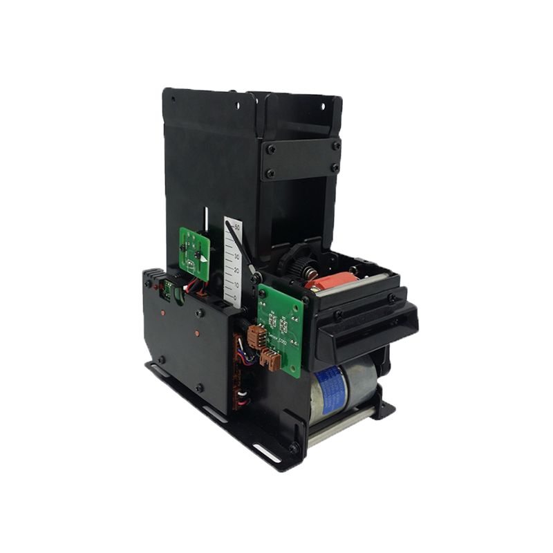
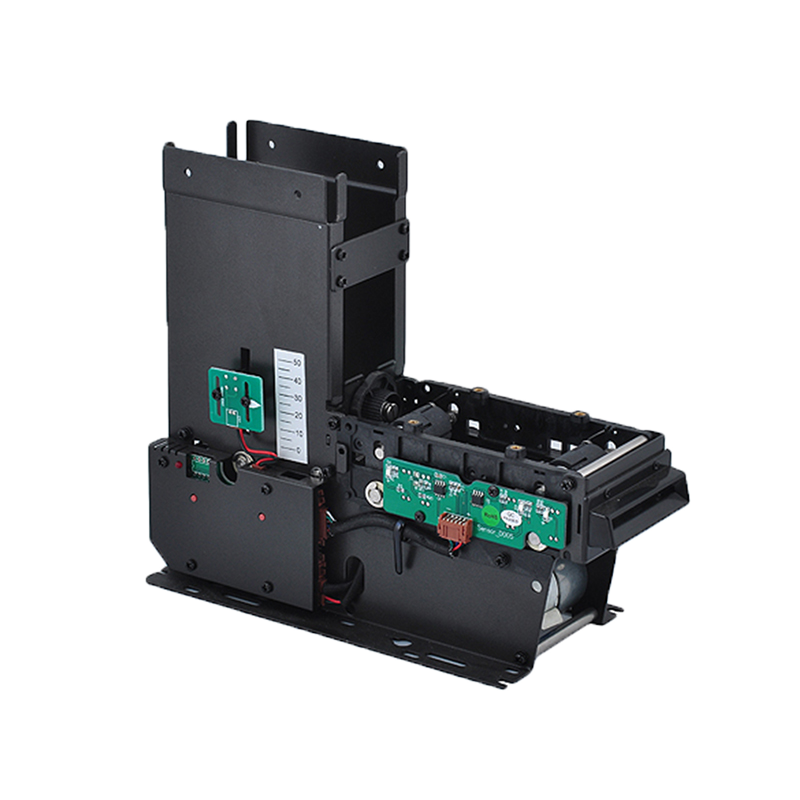

An RFID tag may look like a simple adhesive label, plastic block, textile patch, card, or small industrial component.
Inside, however, several electrical and mechanical elements work together to receive radio-frequency energy, process commands, store data, and communicate with an RFID reader.
At its most basic level, a passive RFID tag contains:
RFID Chip + Antenna + Substrate
A finished RFID product may then add additional layers such as:
These construction differences explain why two RFID tags using similar chips can behave very differently in the same application.
Tag construction affects:
Understanding RFID tag construction is therefore important when selecting tags for retail inventory, manufacturing, logistics, tools, laundry, metal assets, high-temperature equipment, and other industrial applications.
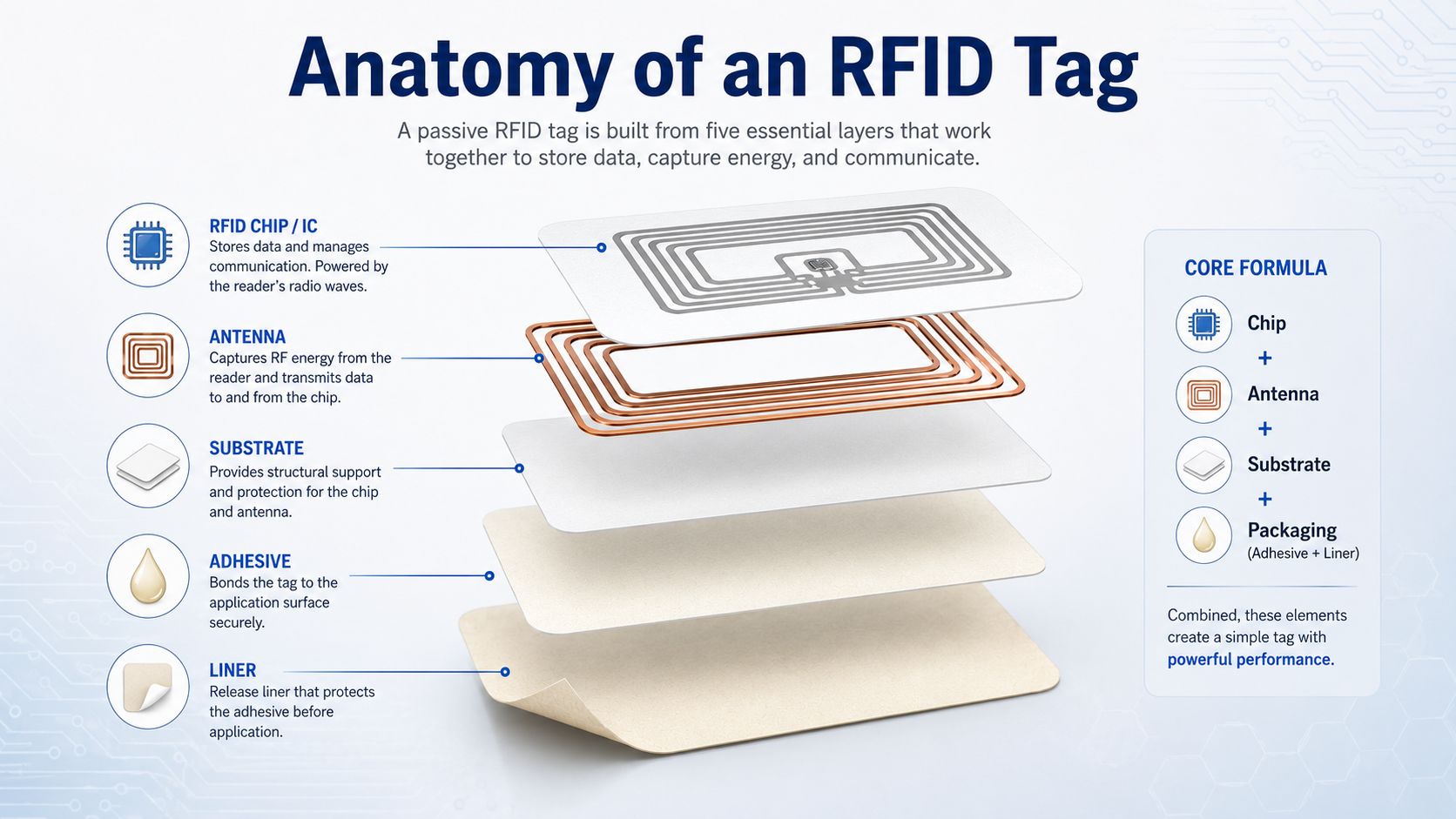
The basic architecture of a passive RFID tag can be simplified as:
RFID Tag = IC + Antenna + Carrier/Substrate + Application-Specific Packaging
The exact structure varies depending on frequency and application, but four elements are particularly important.
The RFID chip, also called an integrated circuit or IC, is the electronic control center of the tag.
It manages functions such as:
Passive RFID tags do not normally contain their own battery.
Instead, the tag receives energy from an RFID reader and uses that energy to power the IC.
The antenna interacts with the RFID reader's electromagnetic field.
Depending on the RFID technology, the antenna can:
For passive UHF RFID, the tag returns information primarily through backscatter modulation.
You can learn more about this communication mechanism in Syncotek's guide to RFID backscatter.
The substrate provides mechanical support for the RFID antenna and chip.
Common materials may include:
For a basic RFID inlay, the chip and antenna are mounted on this carrier.
Commercial RFID inlays are commonly supplied in dry, wet, and finished label formats. Avery Dennison, for example, describes a dry inlay as the inlay carrier, chip, and antenna, while a wet inlay adds pressure-sensitive adhesive and a release liner.
The chip and antenna may need additional protection depending on the application.
A disposable retail tag may require little more than a printable label.
An RFID tag installed on industrial machinery may require:
This is why the external appearance of RFID tags can vary dramatically even when they use related RF technologies.
The RFID IC is extremely small compared with the complete tag, but it performs most of the electronic processing.
In a passive UHF RFID tag, the chip normally contains an RF front end, memory, command-processing logic, power-management circuits, and circuitry used to change the antenna load during backscatter communication.
When a passive RFID tag enters a reader field, the chip can:
The reader does not simply "detect the chip."
The chip and antenna must work as one RF system.
Depending on the chip and protocol, an RFID tag may contain several memory areas.
For EPC Gen2 UHF tags, commonly discussed memory areas include:
Stores the Electronic Product Code or another application identifier used for item identification.
TID means Tag Identifier.
It normally contains information related to the chip manufacturer, model, and tag identity.
Some chips include additional writable memory for application-specific data.
Not every UHF chip provides the same amount of user memory.
Typically associated with access and kill passwords in Gen2 tags.
Different chip models provide different memory capacities and functions. Current commercial UHF inlays, for example, may use NXP UCODE or Impinj chips with different EPC and TID configurations while sharing the same general UHF operating environment.
For a more detailed explanation of writing data to tags, see How to Program an RFID Tag.
RFID tag construction also depends heavily on how the tag is powered.
A passive tag contains no continuous internal battery for normal RF communication.
The reader supplies the energy required for operation.
This allows passive tags to be:
An active RFID tag contains a battery.
The housing therefore needs additional space for:
This results in a substantially different tag construction.
For most item-level retail, supply-chain, and passive UHF applications discussed in this article, the focus is on passive RFID.
The antenna is one of the most important factors determining real-world RFID performance.
Its size, shape, conductive material, frequency tuning, and relationship with the chip all affect tag behavior.
A tag antenna is not simply a piece of metal attached to the IC.
It is an RF structure designed for a particular:
For the tag to use incoming RF energy efficiently, the antenna must be electrically matched to the RFID chip.
Poor matching can reduce the amount of energy reaching the chip.
This may lead to:
This is one reason two tags containing the same chip can have very different read ranges.
The antenna design around that chip may be completely different.
Passive UHF RFID tags commonly use variations of dipole-style antennas.
Examples include:
The shape is optimized according to the required:
RFID antennas can be manufactured from conductive materials such as:
Aluminum is widely used in high-volume RFID inlays because it can provide good RF performance at competitive manufacturing cost.
Commercial UHF inlays are available with very different antenna dimensions even when they use the same chip. For example, current UCODE 9 inlays range from compact circular designs to much larger elongated antennas, illustrating how antenna geometry is selected around the application rather than the chip alone.
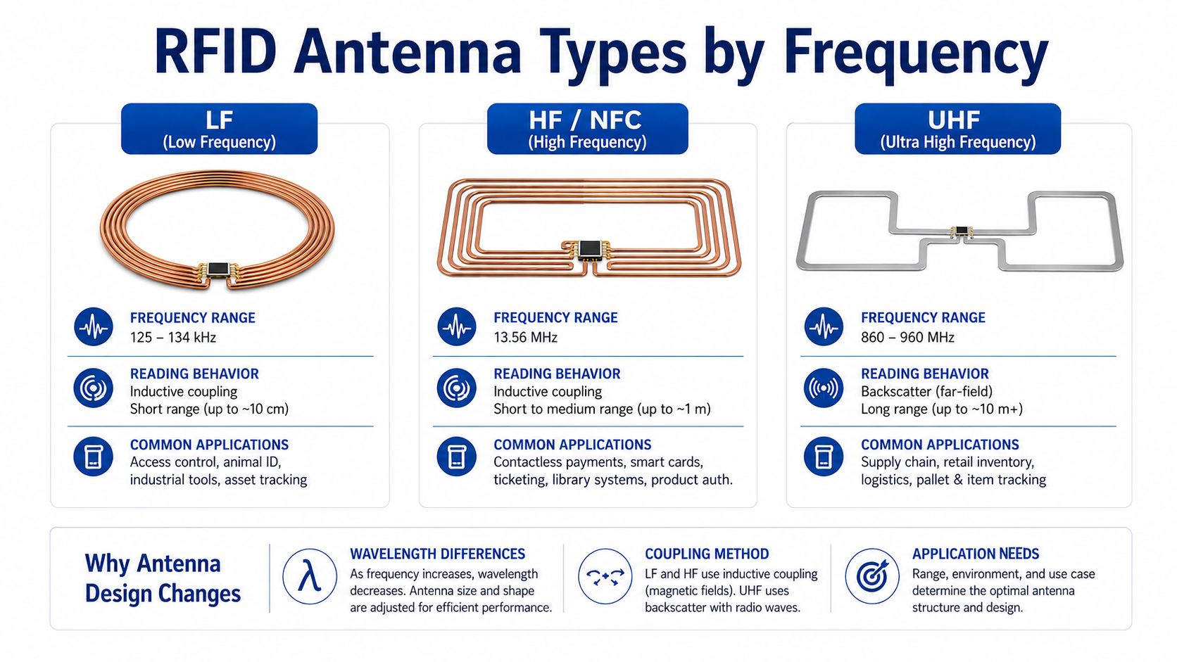
RFID tags operating at different frequencies require different antenna structures.
Low-frequency RFID typically operates around 125 kHz or 134.2 kHz.
LF tags generally use coil antennas and near-field inductive coupling.
Common applications include:
Because LF wavelengths are very long compared with the physical tag, the antenna normally consists of multiple coil turns.
HF RFID and NFC normally operate at 13.56 MHz.
These tags also commonly use multi-turn coil antennas.
Typical applications include:
The tag interacts with the reader mainly through near-field magnetic coupling.
Passive UHF RFID commonly operates within regional bands across approximately 860–960 MHz.
Commercial UHF inlays are designed for the applicable regional band and commonly use dipole-style antennas rather than multi-turn coils.
Typical UHF applications include:
UHF RFID uses far-field communication and backscatter over much longer potential distances than LF or HF systems.
The substrate is the carrier supporting the antenna and IC.
Although it may look insignificant, substrate selection affects:
Flexible RFID inlays commonly use polymer film or paper-type carriers.
PET has traditionally been widely used because it provides:
However, RFID suppliers are increasingly introducing alternative constructions aimed at reducing PET content and environmental impact.
The antenna geometry must remain close to its intended design.
If a substrate stretches, shrinks, bends excessively, or changes dimensions during manufacturing, it can affect antenna tuning.
For applications involving:
a more specialized substrate or encapsulated tag may be required.
The IC must be electrically connected to the antenna.
This connection is one of the smallest yet most critical parts of an RFID inlay.
Commercial RFID production commonly uses high-speed chip-attachment processes, including flip-chip attachment with conductive adhesive or related bonding technologies.
The general structure is:
RFID IC
↓
Electrical Bond
↓
Antenna Contact Pads
↓
RFID Antenna
The connection must remain reliable through:
A failure at the chip-to-antenna connection can make the entire RFID tag unreadable.
RFID tags can use different chip-attachment architectures.
The IC is connected directly to the antenna.
This can reduce material and simplify the final structure.
The IC is first attached to a small intermediate conductive structure called a strap.
The strap is then connected to the larger antenna.
Straps can simplify handling of extremely small IC dies and support certain high-volume manufacturing processes.
The exact method depends on:
An RFID inlay is the functional electronic core from which many RFID labels and tags are produced.
Its essential elements are:
However, inlays are supplied in different conversion formats.
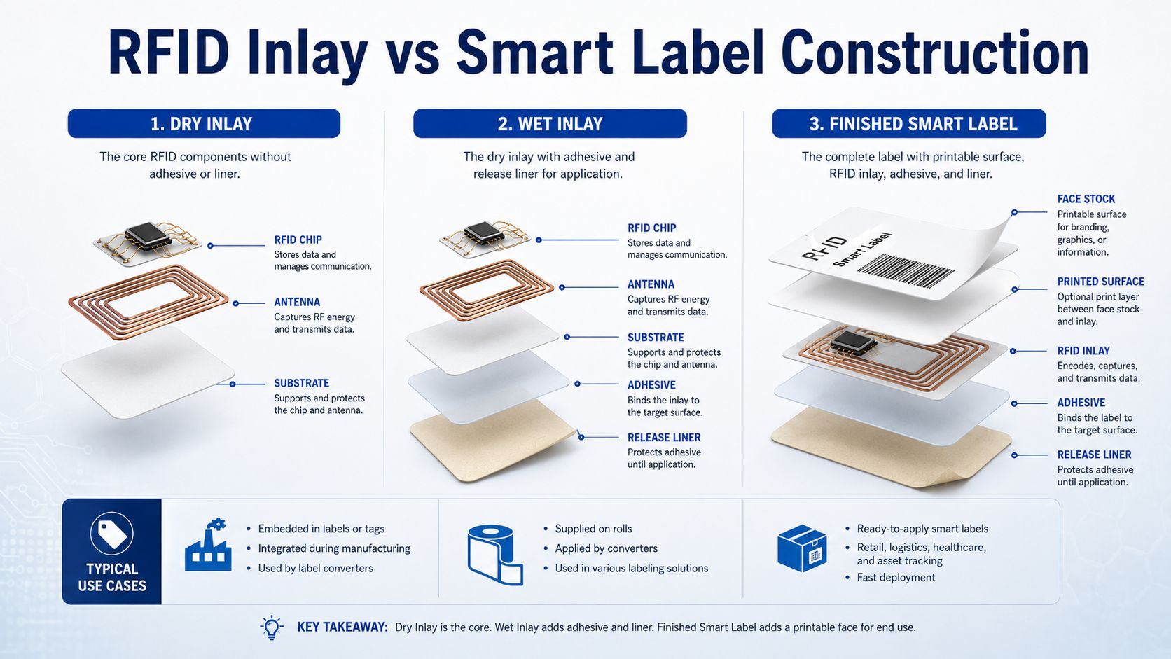
A dry inlay generally consists of:
Carrier + Antenna + RFID Chip
It does not normally include the final pressure-sensitive adhesive and release liner used to attach the tag directly to a product.
Dry inlays are useful for label converters because they allow additional flexibility in choosing:
Avery Dennison similarly defines dry inlays as the carrier, chip, and antenna without the pressure-sensitive adhesive and liner used in wet formats.
A wet inlay adds:
This makes the RFID inlay easier to apply directly or integrate into another converted construction.
A finished smart label usually adds printable face stock above the RFID inlay.
Its simplified construction can be represented as:
Printable Face Stock
↓
RFID Inlay
↓
Adhesive
↓
Release Liner
The face stock can support:
Avery Dennison's current converter guide describes finished label/sticker inlays as adding a printable face stock to the chip, antenna, carrier, adhesive, and liner structure.
For a dedicated comparison of these product formats, see Syncotek's guide to RFID Inlays, Tags, and Labels.
The electronic inlay alone is not suitable for every application.
A thin retail label may work well on a cardboard box but fail quickly when installed:
Additional packaging protects the RFID electronics and modifies RF behavior where necessary.
Possible materials include:
The final packaging can protect against:
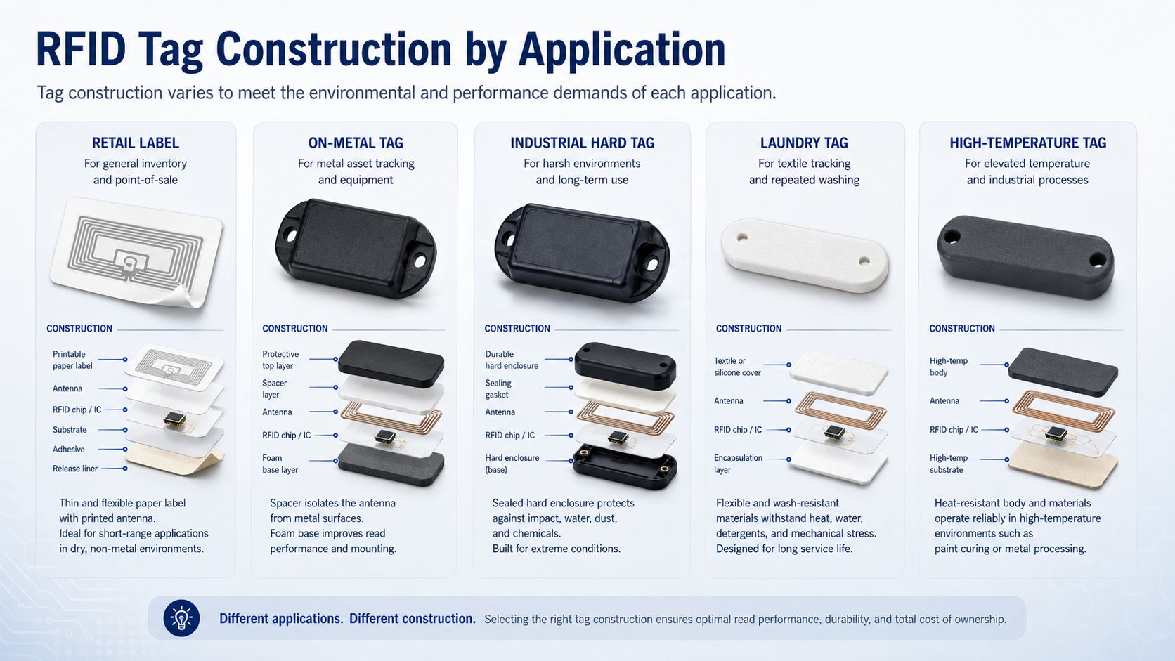
There is no universal RFID tag construction suitable for every product.
Different applications require different structures.
A typical retail UHF label may include:
Important goals include:
Common applications include:
Metal requires a very different design.
A conventional RFID inlay placed directly on metal can become detuned and may provide extremely poor performance.
An on-metal tag can include:
In some designs, the nearby metal surface effectively becomes part of the overall RF structure.
For more detail, see Mount-on-Metal RFID Tags: How to Track Metal Assets Effectively.
Industrial tags may use:
They are designed for longer service life and harsher environments.
Typical applications include:
Syncotek's UHF Tag category includes multiple hard-tag formats for industrial and asset-identification applications.
Laundry tags must survive conditions very different from ordinary labels.
They may need to withstand:
Common constructions include:
See Syncotek's RFID Laundry Tags guide for a detailed overview of washable RFID tag selection.
High-temperature tags may use:
Applications can include:
The complete construction must survive the temperature, not only the RFID chip.
The substrate, adhesive, housing, and attachment method all matter.
On-metal RFID tags deserve special attention because they demonstrate clearly how mechanical construction and RF performance are connected.
A standard UHF label typically expects a relatively RF-friendly surrounding environment.
Metal changes that environment dramatically.
It can:
An on-metal tag therefore uses a structure designed specifically around the conductive surface.
A simplified construction can be:
Protective Housing
↓
RFID Antenna + IC
↓
Dielectric / Spacer Layer
↓
Metal Asset
The spacer separates the antenna from the conductive surface and allows the antenna to operate within its intended RF design.
The exact structure varies significantly between manufacturers and tag types.
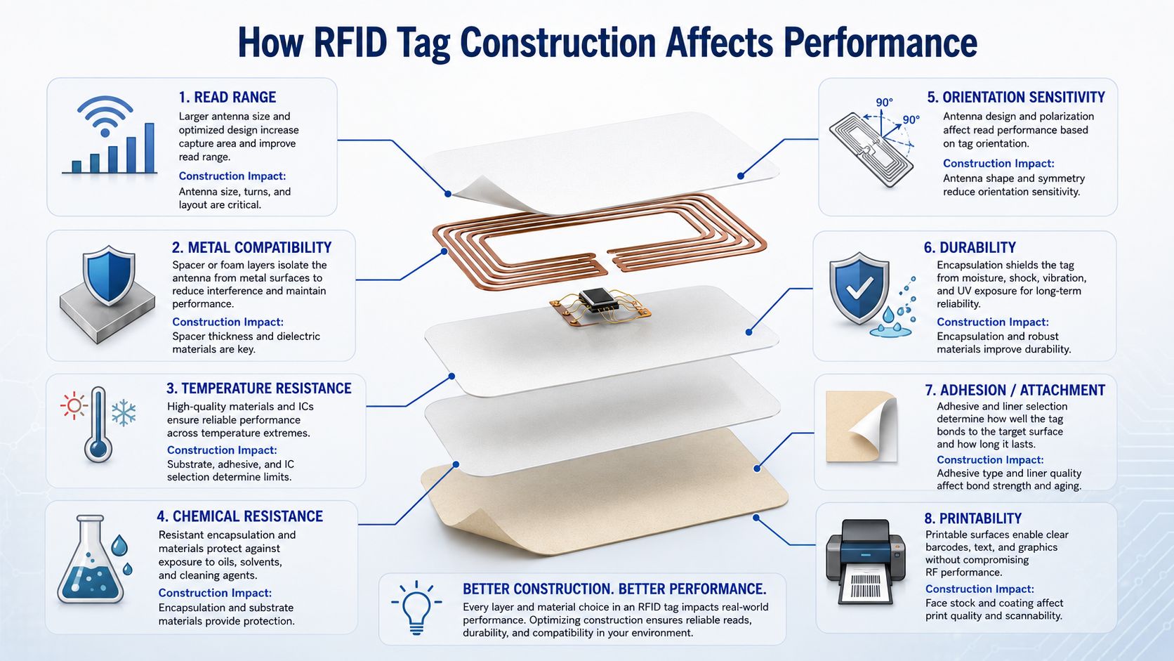
RFID performance is determined by the complete tag, not by one specification.
Read range can be influenced by:
A larger antenna may capture more RF energy, but size alone does not guarantee better performance.
Antenna tuning and application environment are equally important.
Some RFID tags are optimized for narrower regional bands.
Others are designed for broader global UHF operation.
A wider operating bandwidth may be useful for products that move internationally between different RFID regulatory regions.
On-metal performance depends on:
A conventional paper RFID label and a rugged on-metal tag can contain similar protocol-compatible chips but have completely different RF performance on a steel asset.
Temperature limits depend on more than the IC.
They can also depend on:
A heat-resistant chip inside an adhesive label that fails at high temperature does not create a high-temperature RFID tag.
Tags used in industrial environments may encounter:
Protective encapsulation and housing material determine whether the tag remains mechanically and electrically stable.
Tag antenna design affects how orientation changes read performance.
For UHF tags, the relationship between tag polarization and reader antenna polarization is particularly important.
A tag may perform well in one orientation but poorly after being rotated.
Mechanical durability depends on:
A retail label may only need to survive through purchase.
An industrial asset tag may need to remain usable for years.
Adhesive is part of RFID tag engineering.
A perfectly tuned tag that falls off the asset cannot provide reliable identification.
Attachment options can include:
Dry inlays can also allow converters to choose specialized adhesives for challenging surfaces, high or low temperatures, moisture, and removable applications.
Smart-label construction must support both RFID and visual identification.
The face material may need to support:
The RFID inlay position must also be compatible with the RFID printer encoder.
One of the most important RFID selection principles is:
RFID tag performance is not determined by the chip alone.
Consider two UHF tags using the same IC.
Tag A may have:
Tag B may have:
Even though the underlying IC is the same, the tags may differ significantly in:
A more accurate way to think about RFID performance is:
Tag Performance = Chip + Antenna + Matching + Construction + Product + Environment
This is why choosing tags solely by chip model can lead to poor deployment results.
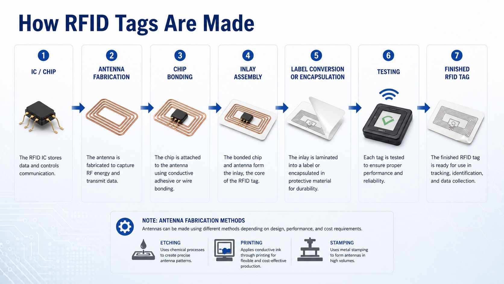
RFID tag manufacturing differs by technology and final product, but a passive RFID inlay generally follows several major stages.
RFID chips begin as semiconductor wafers.
The semiconductor process creates the circuitry needed for:
The wafers are then processed into individual dies.
The antenna pattern is produced separately.
Possible manufacturing methods include:
The most appropriate process depends on:
The RFID die is electrically bonded to the antenna.
High-volume inlay production requires very precise positioning because the chip connection points are extremely small.
Once the chip and antenna are connected, they form the functional RFID inlay on the carrier.
At this stage, the RFID element can be electrically tested.
The inlay is converted into the required final product.
For smart labels, this may involve:
For industrial tags, the RFID electronics may instead be:
Manufacturing quality control may evaluate:
Testing helps identify defective inlays before they are converted or deployed.
The final product can then be supplied as:
Tag selection should start with the application, not with a catalog part number.
For example:
| Requirement | Construction Direction |
|---|---|
| Low-cost apparel tagging | Thin UHF smart label |
| Cardboard carton | Adhesive UHF label |
| Metal tool | On-metal rugged tag |
| Repeated laundry | Washable textile/silicone/PPS tag |
| High-temperature manufacturing | Heat-resistant encapsulated tag |
| Outdoor industrial asset | UV/weather-resistant hard tag |
| Disposable package | Lightweight label |
| Long-life equipment | Rugged mechanically attached tag |
The best RFID tag is the one whose electrical and mechanical construction matches the real environment.
Before selecting an RFID tag, define the following.
Is the tag applied to:
This is one of the most important factors in tag selection.
Determine whether the application requires:
The antenna architecture is completely different between these technologies.
Do you need:
Do not select a long-range tag simply because it has the highest quoted distance.
The read zone should match the business workflow.
Consider:
Is the tag needed for:
Options include:
Mechanical attachment can be more reliable for long-life industrial assets.
Smaller is not always better.
Reducing tag dimensions can affect:
Choose the smallest tag that still meets the required RF performance.
If the RFID tag will be printed and encoded through an RFID printer, confirm:
The IC is only one part of RFID performance.
Always evaluate the complete tag design.
Protocol compatibility does not mean identical RF performance.
Two EPC Gen2 tags can have very different antennas and application targets.
An RFID label can perform very differently after attachment to the actual product.
Test on the final object.
Metal can severely detune conventional UHF labels.
Use a tag designed for metal or another validated mounting solution.
An RFID tag that separates from the product creates an identification failure even if the electronics still work.
Test all realistic product orientations.
Verify the complete tag construction, not only the chip specification.
A compact tag may sacrifice performance.
Select dimensions based on the application.
Tag performance cannot be evaluated independently of the RFID reader system.
Reader power, antenna gain, polarization, and installation geometry all affect the result.
Before approving an RFID tag, confirm:
RFID tags may appear simple from the outside, but their performance depends on a carefully designed combination of electronic and mechanical components.
The functional core is:
RFID Chip + Antenna + Substrate
From there, additional layers transform the inlay into a practical product:
Adhesive + Face Stock + Liner + Spacer + Housing + Encapsulation + Attachment
Each element has a purpose.
The chip controls communication and memory.
The antenna determines how effectively the tag interacts with RF energy.
The substrate supports the electrical structure.
Packaging protects the tag and adapts it to the target environment.
This is why there is no single universal RFID tag.
A lightweight retail label, washable laundry tag, rugged industrial tag, and metal-mount tag may all use compatible RFID protocols while having completely different physical constructions.
When selecting RFID tags, do not ask only:
Which RFID chip does this tag use?
Also ask:
The complete tag construction determines whether an RFID system works reliably outside the laboratory.
A basic passive RFID tag contains an integrated circuit or chip, an antenna, and a supporting substrate. Finished tags may also include adhesive, liner, face stock, protective housing, spacers, or other application-specific materials.
A passive tag contains an RFID IC and antenna but does not normally require a battery for communication. It obtains operating energy from the RFID reader field.
The RFID chip manages memory, protocol communication, command processing, power management, and tag responses.
The antenna receives RF energy and reader commands. In passive UHF RFID, it also helps return data through backscatter modulation.
The substrate is the carrier material that supports the RFID antenna and chip. Flexible inlays commonly use film or paper-type substrates.
An RFID inlay is the functional electronic core consisting primarily of the RFID chip, antenna, and supporting carrier.
A dry inlay normally contains the carrier, antenna, and chip without pressure-sensitive adhesive. A wet inlay adds adhesive and a release liner.
An RFID smart label combines an RFID inlay with a printable label construction, usually including face stock, adhesive, and release liner.
Common conductive materials include aluminum, copper, and conductive inks.
Antenna geometry is designed according to operating frequency, chip impedance, physical size, bandwidth, orientation, read-range requirements, and target material.
LF and HF systems generally operate through near-field inductive coupling, so multi-turn coil antennas are commonly used.
Passive UHF RFID operates primarily through far-field electromagnetic communication and backscatter, so dipole-style antenna structures are common.
Metal changes the RF field and can detune a conventional tag antenna. On-metal tags use specially engineered antenna and spacer structures to work reliably on conductive surfaces.
Yes. Antenna design, impedance matching, physical size, substrate, tagged material, orientation, and packaging can all create significant performance differences.
Some are, but not all. A paper smart label normally has very different environmental protection from an encapsulated industrial hard tag.
Typical production includes IC fabrication, antenna production, chip attachment, inlay assembly, label conversion or encapsulation, testing, and final finishing.
Use an RFID tag specifically designed for metal surfaces and test it on the actual asset. Standard UHF labels usually should not be placed directly on metal without a validated spacer or special design.
Base the decision on frequency, product material, read range, environment, service life, size, attachment method, printing requirements, and real-product RFID testing.
Syncotek provides UHF RFID tags and complementary RFID hardware for retail inventory, manufacturing, logistics, industrial assets, tools, reusable equipment, and other automatic-identification applications.
The Syncotek RFID portfolio includes:
Different products and environments require different tag structures.
A paper label for apparel should not be selected the same way as a tag for a steel machine, reusable industrial container, or high-temperature production process.
Explore Syncotek's UHF RFID Tags or browse the complete RFID product portfolio to evaluate suitable tag and reader configurations for your application.
 Knowledge
UHF RFID systems use radio waves to communicate between readers, antennas, and passive RFID tags. In a small installation with one reader, radio-frequency interference may be relatively easy to control. In a warehouse, factory, retail store, distribution center, or event venue with several readers operating at the same time, the RF environment becomes more complicated. […]
READ MORE Knowledge
A successful RFID project should not begin by purchasing readers. It should begin with a business problem. Companies often approach RFID projects with a requirement such as: We want to use RFID in our warehouse. That is not yet an RFID requirement. A much more useful project definition would be: We need to verify whether […]
READ MORE Case Show
Cloud printing is a printing technology based on cloud services, which can be well matched with Internet applications.
READ MORE Knowledge
The RFID system auto-identifies vehicles' weight, calculates net weight, and provides real-time monitoring for optimized efficiency.
READ MORE Knowledge
Metal asset tracking is one of the most important applications in RFID, but it is also one of the most technically challenging. Many companies want to use RFID to identify tools, machines, containers, laptops, racks, returnable transport items, and industrial equipment, only to discover that standard RFID labels do not perform well when placed directly […]
READ MOREIf you are interested in our services or need customized solutions, please feel free to contact us.