

An RFID system may work perfectly during initial testing and then behave very differently after it is installed in a warehouse, factory, smart cabinet or production line.
Common symptoms include:
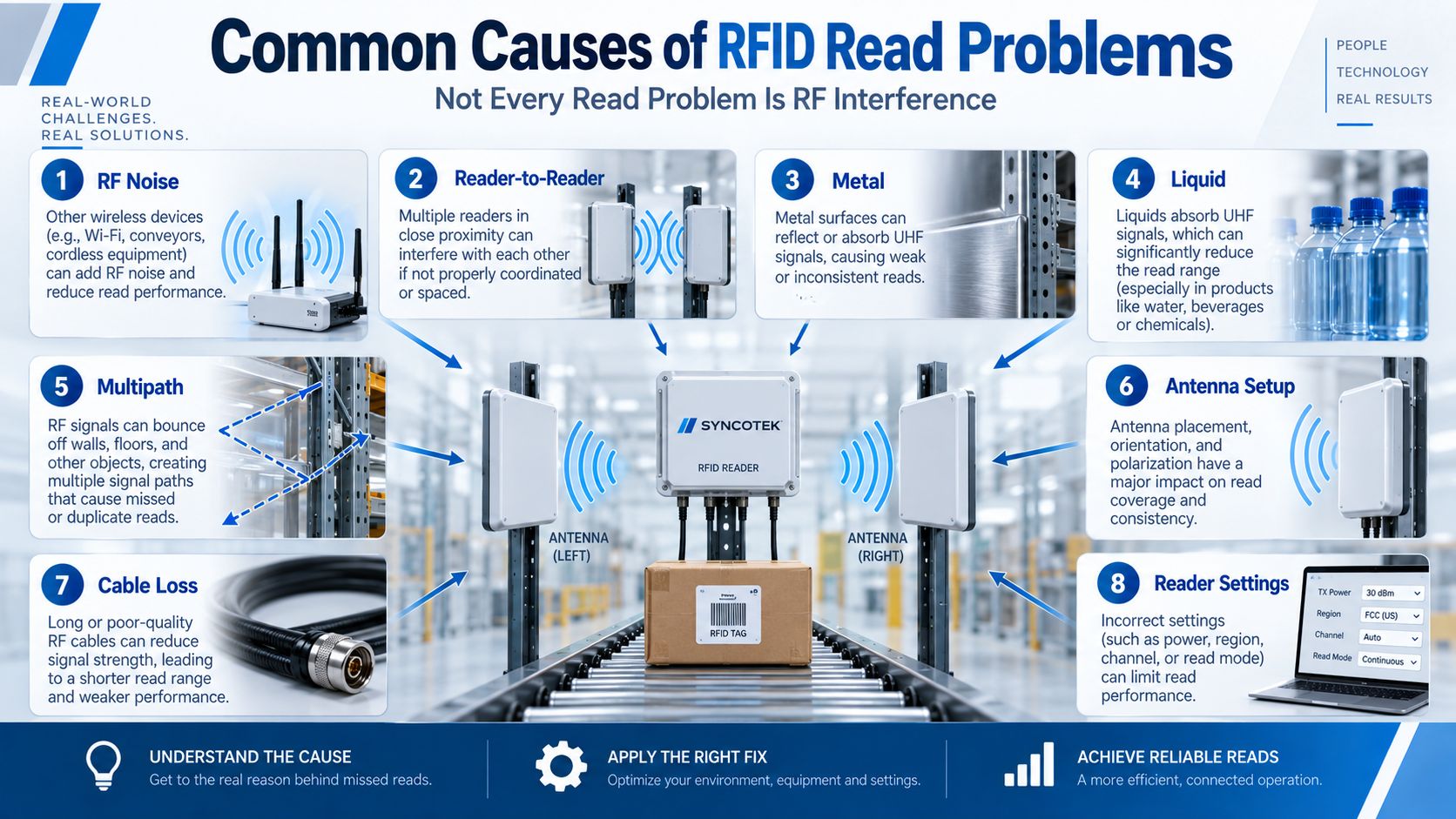
These problems are frequently described as RFID interference.
But that description is often too broad.
Not every RFID read problem is RF interference.
The real cause may instead be:
The symptoms may look similar, but the solutions are completely different.
A better troubleshooting process is:
Define the Symptom
→ Check the Tag
→ Check the Tagged Material
→ Check Antenna and Cable
→ Check Reader Settings
→ Check the RF Environment
→ Check Other Readers
→ Check Software
→ Validate the Real Workflow
The objective is not to make the RFID reader transmit as strongly as possible.
The objective is to create a repeatable and controlled RFID read zone.
RFID troubleshooting becomes easier if we separate three different categories of problems.
RF interference occurs when unwanted RF energy affects communication between the RFID system components.
Examples include:
This is interference in the traditional RF sense.
The environment can also alter how RF energy travels.
Examples include:
These are not necessarily external interference sources.
They are propagation effects.
Many issues that appear to be interference are actually configuration problems.
Examples include:
Correct diagnosis matters because each category requires a different fix.
| Symptom | Likely Causes |
|---|---|
| Short read range | Tag/material mismatch, cable loss, low power, antenna issue |
| Intermittent reads | Orientation, multipath, weak RF margin, movement |
| Tags read outside zone | Excessive power, reflections, antenna beam, no trigger |
| Some tags always missed | Placement, metal/liquid, orientation, tag shielding |
| Works with one reader but not several | Reader-to-reader interference |
| Works stationary but fails moving | Short dwell time, throughput, narrow zone |
| Read range suddenly changes | Cable, connector, environment, antenna movement |
| Duplicate application events | Middleware / filtering logic |
| Wrong location assigned | Antenna mapping / zone logic |
| Strong nearby tags but weak target reads | Poor read-zone design or propagation |
The most important troubleshooting principle is:
Identify the type of failure before changing hardware.
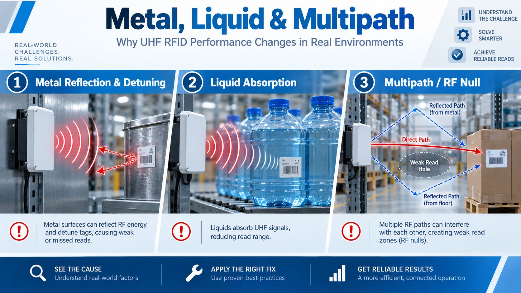
Metal and water-rich materials are among the most common reasons UHF RFID performs differently in the field than on a test bench.
Passive UHF / RAIN RFID operates in the UHF band, and practical range depends heavily on the operating environment. GS1 specifically notes that passive UHF performance and range vary according to environmental conditions.
Metal can affect RFID in several ways.
A conventional UHF label antenna is designed to operate under particular electrical conditions.
Placing it directly against metal can change those conditions and dramatically reduce performance.
Symptoms include:
Metal can also reflect reader RF energy.
This may:
Possible fixes include:
For metal applications, see Mount-on-Metal RFID Tags.
Water-rich materials can absorb UHF RF energy.
Examples include:
A tag that reads well on an empty plastic bottle may perform differently after the bottle is filled.
Possible solutions include:
The correct RFID tag should always be tested on the final product.
See How to Choose the Right RFID Tag for a complete selection process.
Multipath occurs when an RF signal reaches the tag or reader through multiple paths.
For example:
Direct Path
Reader → Tag
and
Reflected Path
Reader → Metal Rack → Tag
or:
Reader → Floor → Tag
The signals arrive with different phases.
Depending on their relationship, the result can be:
Signals reinforce one another.
RF energy becomes stronger in a particular location.
Signals partially cancel.
This can create:
Impinj's deployment guidance similarly emphasizes that real installations must be tested in their actual coverage environment because construction materials, positioning and surrounding conditions affect coverage.
Try changing one variable at a time:
Circular polarization can improve orientation tolerance in some applications, but it does not eliminate multipath.
For antenna-selection guidance, see How to Select the Right RFID Antenna.
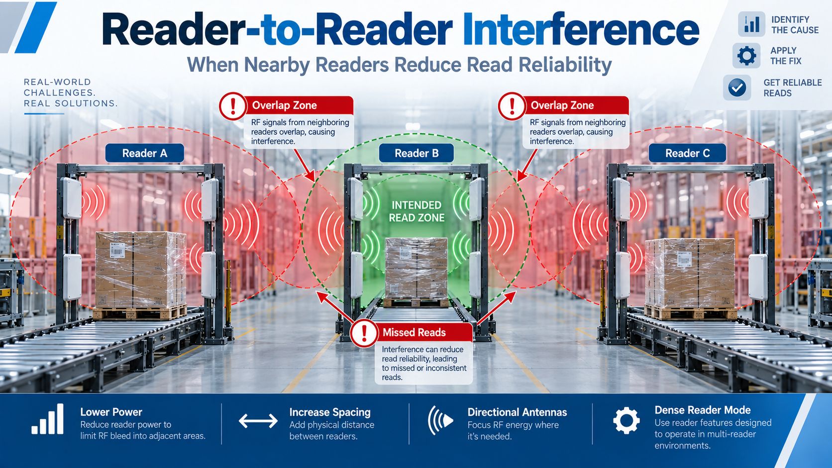
Reader-to-reader interference becomes increasingly important when many UHF RFID readers operate close together.
Consider three warehouse portals:
Reader A
Reader B
Reader C
Each transmits significantly more RF energy than the very weak backscatter signal returned by passive tags.
If reader coverage is poorly controlled, transmission from one system can interfere with reception or tag operation in another nearby system.
Do not automatically run every reader at maximum output.
Impinj explicitly recommends tuning transmit power to reduce stray tags and reader interference in dense-reader environments.
Where possible, increase distance between:
Point RF energy toward the intended zone rather than toward another reader installation.
Higher antenna gain is not automatically better.
A well-controlled beam can be more valuable than maximum coverage.
Reader mode, sessions and other parameters may need to be tuned for dense deployments.
Passive UHF RFID standards include mechanisms intended for environments where many readers operate near one another.
The current GS1 EPC UHF Gen2 standard is Release 3.0.1, ratified in February 2026, and continues to define dense-interrogator operation for UHF RFID systems.
Dense-reader mechanisms help RFID systems coexist more effectively by managing reader and tag communication within crowded RF environments.
However:
Dense Reader Mode is not a substitute for good RF design.
You still need to manage:
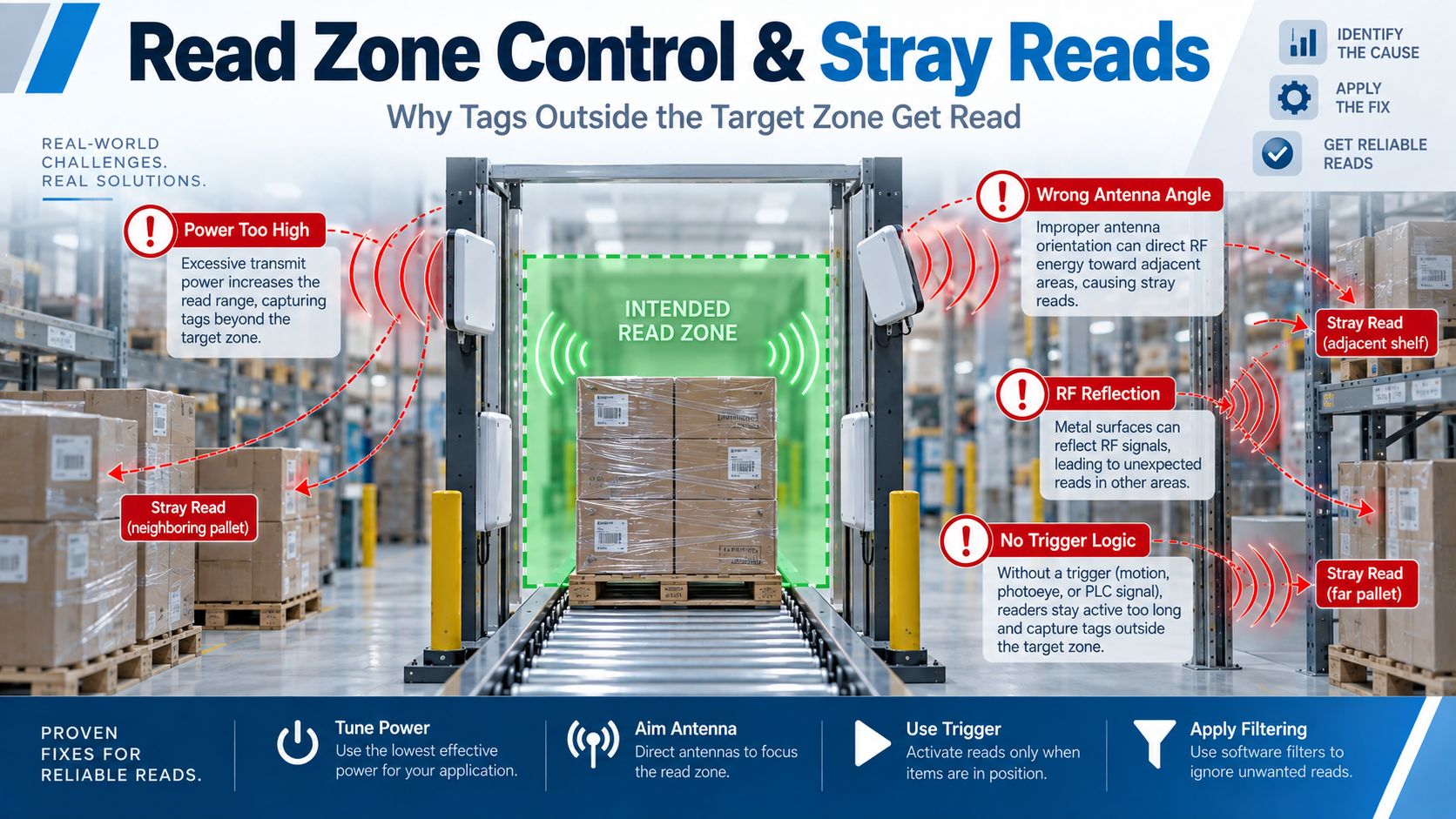
Stray reads occur when the reader detects a valid RFID tag that is not part of the intended process event.
For example:
A pallet is moving through Shipping Door A.
The system correctly reads that pallet.
But it also reads:
The RFID reader itself may be working perfectly.
The problem is the read zone.
More RF power increases the area in which tags can potentially respond.
RF energy may point toward unwanted inventory.
The coverage pattern may extend farther than required.
Metal walls, shelving or machinery can redirect energy.
A continuously running reader may capture tags before or after the intended physical event.
Software may treat every visible tag as part of the transaction.
Use the lowest power that reliably captures the intended tags.
Adjust:
A photoelectric sensor can activate the RFID read process only when a pallet enters the correct position.
Example:
Sensor Detects Pallet
→ Reader Inventory Starts
→ Tags Captured
→ Reader Event Ends
Software can combine:
to determine which reads actually belong to the event.
GS1's Gen2v3 evolution also includes mechanisms designed to improve handling of fringe tags around read zones, but physical RF design remains essential.
Antenna problems are frequently misdiagnosed as reader problems.
Important variables include:
An antenna may be physically above or below the strongest tag path.
The beam may point toward:
rather than the desired products.
A linearly polarized antenna performs best when tag orientation aligns appropriately.
If tag orientation is unpredictable, performance can vary sharply.
Circular polarization can provide better orientation tolerance in many applications.
Mounting an antenna directly beside a large reflective structure can alter its effective radiation environment.
Adding more antennas can sometimes create:
Another antenna is not automatically the solution.
RF power is one of the easiest settings to change, which means it is also one of the most frequently misused.
Possible symptoms:
Possible symptoms:
The correct objective is:
Reliable reads inside the required zone with minimal reads outside it.
Not:
Maximum possible transmit power.
For more information, see How to Choose a UHF RFID Fixed Reader.
Sometimes the problem is not interference at all.
It is the physical RF path.
A fixed RFID installation often looks like:
Reader
→ RF Cable
→ Antenna
Every cable introduces insertion loss.
Longer cables generally increase total loss.
Additional:
can further reduce performance.
If several antennas use identical settings but one performs very differently, swap cables or antennas systematically to isolate the fault.
See RFID Cables, Connectors and Adapters.
The tag itself contains an antenna.
Its relationship to the reader antenna affects communication.
A tag may perform well:
but poorly:
depending on system polarization and geometry.
Placement on the same product also matters.
For example:
A carton label placed at:
may produce very different results.
Tag placement should become part of the production SOP after testing.
Passive UHF Gen2 includes anti-collision mechanisms designed to inventory multiple tags.
So it is not technically accurate to say:
There are many tags, therefore they all simply collide and cannot be read.
The real problem is more nuanced.
Large tag populations can challenge the system because of:
Impinj's portal configuration guidance explicitly recommends tuning estimated tag population, search mode, session and transmit power according to the number of tags and portal environment.
A pallet contains 500 tags.
The pallet remains in the portal for only two seconds.
The reader does not simply need:
High read range.
It needs:
A system may achieve excellent performance in a stationary test and then fail in production.
Why?
Because movement changes the available reading time.
Product remains inside antenna coverage for 10 seconds.
Product passes through in 0.8 seconds.
The reader has far fewer opportunities to inventory the tags.
This is why an RFID pilot must reproduce real movement.
See How to Start an RFID Project for the complete PoC and pilot methodology.
External electromagnetic noise can also affect RFID systems.
Possible sources may include:
However, do not automatically blame every wireless technology nearby.
For example, typical Wi-Fi systems operate in frequency bands different from passive UHF RFID's 860–930 MHz air-interface range. UHF RFID interference should therefore be diagnosed rather than assumed simply because Wi-Fi equipment is present.
If external RF noise is suspected:
A spectrum analyzer can help determine whether significant RF energy exists in the relevant RFID operating band.
Passive UHF RFID does not use exactly the same operating rules worldwide.
Reader configuration must comply with the deployment region.
Examples include different allocations and power/channel regulations in:
The GS1 Gen2 standard defines the UHF air interface across the broader 860–930 MHz range, while actual reader operation must follow local regulatory requirements.
Do not solve performance problems by arbitrarily switching to frequencies not permitted in the deployment country.
Reader and tag selection should be optimized for the actual region.
Some "RFID reading problems" occur after the reader has already captured the EPC correctly.
The reader reports the same tag repeatedly.
This is normal behavior in continuous inventory.
The software needs to determine whether those reads represent:
An overly aggressive filter may discard a legitimate RFID event.
The reader works correctly, but:
The reader or middleware may intentionally ignore tags that do not match a configured filter.
RF communication may be working normally while business events appear late.
The complete troubleshooting process should therefore include:
RF Layer
and
Data Layer
For more detail, see RFID System Architecture.
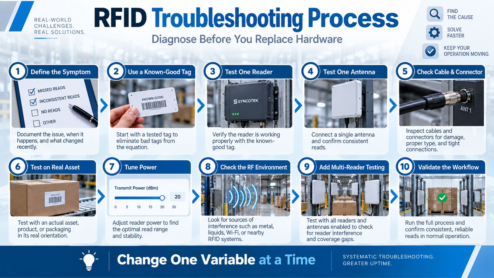
Randomly changing several settings at once is one of the fastest ways to make RFID troubleshooting more difficult.
Use a controlled diagnostic process.
Write down exactly what is wrong.
Avoid:
RFID is unstable.
Use:
Tags on the lower-left side of a pallet are missed when the forklift passes the portal above 5 km/h.
or:
Reader A detects tagged cartons on the rack 3 meters outside the intended doorway zone.
This makes the problem measurable.
Choose one tag that has already demonstrated reliable performance.
This removes unknown tag quality from the first test.
Disable additional readers temporarily.
Verify the core reader works correctly.
Use a single known-good antenna.
This simplifies the RF environment.
Inspect:
Move from:
Tag in free air
to:
Tag installed on the real product.
This immediately reveals many:
issues.
Start at a controlled level.
Increase or decrease in measured steps.
Record:
Reintroduce:
and observe changes.
Activate readers individually.
Then test simultaneous operation.
If performance changes only when another reader is enabled, you have useful evidence of multi-reader interaction.
Finally test:
An RFID system is not validated until it works in its actual workflow.
This rule is fundamental.
Do not simultaneously:
If performance improves, you will not know why.
Instead:
Baseline
→ Change Power
→ Record Result
→ Restore / Keep
→ Change Antenna Position
→ Record Result
This creates evidence rather than guesses.
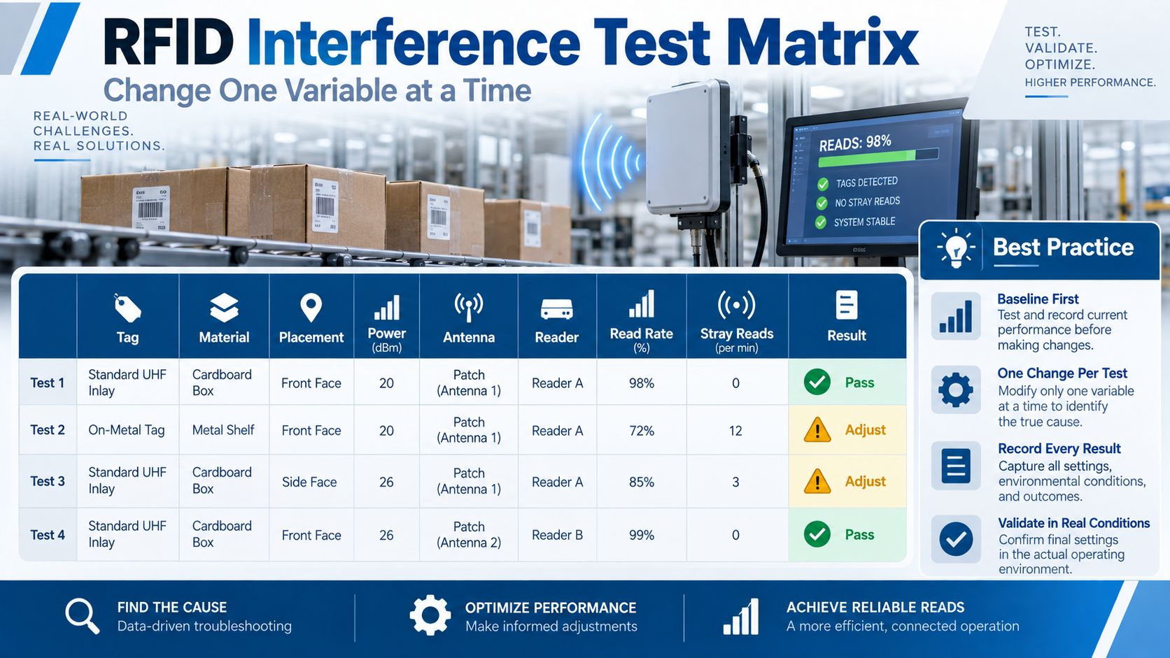
A simple engineering matrix makes troubleshooting far easier.
| Test | Tag | Material | Placement | Power | Antenna | Reader | Read Result | Stray Reads |
|---|---|---|---|---|---|---|---|---|
| Baseline | Tag A | Cardboard | Front | 20 dBm | Ant 1 | Reader A | Record | Record |
| Test 2 | Tag B | Metal | Front | 20 dBm | Ant 1 | Reader A | Record | Record |
| Test 3 | Tag B | Metal | Front | 24 dBm | Ant 1 | Reader A | Record | Record |
| Test 4 | Tag B | Metal | Side | 24 dBm | Ant 1 | Reader A | Record | Record |
| Test 5 | Tag B | Metal | Side | 24 dBm | Ant 2 | Reader A | Record | Record |
Keep other conditions as constant as possible.
Then the team can see which change actually improved performance.
Warehouse portals commonly combine several difficult RF factors:
A good troubleshooting order is:
Do not begin with a fully populated warehouse and change random settings.
Common cabinet symptoms include:
Start by:
In cabinet applications:
Shorter and more controlled RFID range can be better than longer range.
Manufacturing systems may contain:
Test the reader while machinery is:
If RFID performance changes only when specific equipment runs, investigate the RF/electrical environment further.
Typical retail problems include:
The solution may require a combination of:
Healthcare RFID projects require additional attention because RF transmitters may operate near sensitive electronic medical systems.
RFID deployment around medical equipment should consider:
See RFID in Healthcare for broader healthcare RFID design considerations.
RF shielding can be useful, but it should not be the first solution to every problem.
Potential applications include:
Shielding may help physically restrict RF propagation.
However, it can also:
Before adding shielding, first optimize:
Tag
→ Antenna
→ Placement
→ Reader Power
→ Read-Zone Logic
Consider changing the tag when:
The problem may not require a new reader.
Consider changing the antenna when:
Reader tuning may be appropriate when:
Impinj's current configuration examples specifically emphasize tuning transmit power, tag population, sessions and reader mode to the real application rather than relying on one universal setting.
Reader replacement makes more sense when the existing hardware lacks:
Do not replace the reader simply because a tag attached directly to metal performs badly.
Solve the actual root cause.
Before replacing RFID hardware, verify:
RFID interference can come from neighboring RFID readers or other RF energy, but many apparent interference problems are actually caused by metal, liquids, multipath, antenna placement, cable loss, reader settings or software logic.
Possible causes include insufficient RF energy, metal or liquid around the tag, poor orientation, wrong tag type, antenna placement, cable loss, short dwell time or incorrect reader configuration.
Check whether anything changed in the tag placement, product material, antenna position, RF cable, connector, reader power or physical environment.
Metal can detune conventional UHF RFID tags and reflect RF energy. On-metal tags are normally required when tagging conductive surfaces directly.
Water-rich materials can absorb UHF RF energy and reduce practical read range. Tag placement and antenna design should be tested on the real product.
Multipath occurs when RF energy reaches the receiver through both direct and reflected paths. The signals may reinforce or cancel each other, producing stronger areas and RF nulls.
Yes. Nearby readers can affect each other's performance if RF coverage and configuration are poorly controlled.
Dense-reader mechanisms are designed to improve UHF RFID operation when multiple interrogators operate near one another. They do not replace proper antenna placement and RF planning.
GS1's current EPC UHF Gen2 standard is version 3.0.1, published on February 26, 2026.
Yes. Excessive power can increase stray reads, overlapping read zones and interaction with nearby RFID infrastructure.
Typical causes include excessive RF power, antenna direction, reflections, wide antenna coverage and insufficient trigger or event logic.
Wi-Fi should not automatically be assumed to be the cause simply because it is wireless. Passive UHF RFID uses the 860–930 MHz range, while typical Wi-Fi operates in different bands. If external RF noise is suspected, measure the actual spectrum and test the suspected source.
Yes. Tag orientation relative to antenna polarization can significantly affect UHF RFID performance.
Yes. Long, poor-quality or damaged RF cables and connectors can reduce energy delivered to the antenna and weaken the return signal path.
Moving products have less dwell time inside the read zone. Conveyor speed, tag population, antenna coverage and reader settings may need adjustment.
Possible causes include shielding, tag orientation, metal/liquid products, RF nulls, poor tag placement or insufficient time to inventory the full population.
No. Circular polarization can improve tolerance to varying tag orientation, but it does not eliminate multipath, reader interference or poor read-zone design.
Not automatically. First identify whether the problem is power, tag selection, orientation, antenna placement, cable loss, material or another cause. Higher power may create new stray-read problems.
Shielding can help in tightly controlled zones such as cabinets and encoding stations, but tag selection, antenna positioning and power tuning should normally be optimized first.
Test one reader independently, establish a baseline, then activate nearby readers one at a time while monitoring read reliability and stray reads. Adjust power, spacing, antenna direction and reader configuration systematically.
Use real tags, real products, final antenna locations, realistic tag density, production movement and all neighboring readers. Record results while changing only one variable at a time.
Syncotek provides RFID hardware for system integrators, manufacturers, software companies and OEM developers building passive UHF / RAIN RFID systems.
Our product portfolio includes:
When an RFID installation has problems such as:
the fastest path is usually not to replace every component.
Start by documenting:
This makes it possible to narrow whether the problem is primarily associated with:
Tag
Antenna
Cable
Reader Configuration
RF Environment
or
System Architecture
For deeper component-level guidance, continue with:
How to Choose a UHF RFID Fixed Reader
The most reliable RFID systems are not necessarily the systems with the highest transmit power or the most antennas.
They are the systems where the tag, antenna, reader settings, environment and business read zone are engineered to work together.
 Knowledge
RFID tags are electronic identifiers that allow physical products, assets, containers, tools, garments and other objects to communicate wirelessly with an RFID reader. Unlike a barcode, an RFID tag normally does not need to be directly visible to the reader. Depending on the RFID technology and system design, readers can identify individual tags, inventory multiple […]
READ MORE Knowledge
Manufacturing operations depend on accuracy, timing, and visibility. Materials, tools, fixtures, machines, work orders, semi-finished goods, and finished products move through many production stages every day. When these movements are recorded manually, manufacturers often face delayed updates, inventory errors, missing tools, unclear production status, and limited visibility across the shop floor. RFID technology helps manufacturers […]
READ MORE Knowledge
Learn the real differences between RFID and NFC—frequencies, range, security, smartphone compatibility, data models, and use cases. See when to choose UHF RFID (RAIN) vs. NFC, and how Syncotek readers fit your project.
READ MORE Knowledge
An RFID reader and writer is a device that can both read data from RFID tags and write new data into compatible RFID tags. In many RFID projects, this type of device is also called an RFID reader-writer, RFID read-write device, or simply an RFID writer. The “read” function allows the device to detect RFID tags and collect stored information […]
READ MORE Industry Info
How to Choose Frequency for Your Access Control System
READ MOREIf you are interested in our services or need customized solutions, please feel free to contact us.