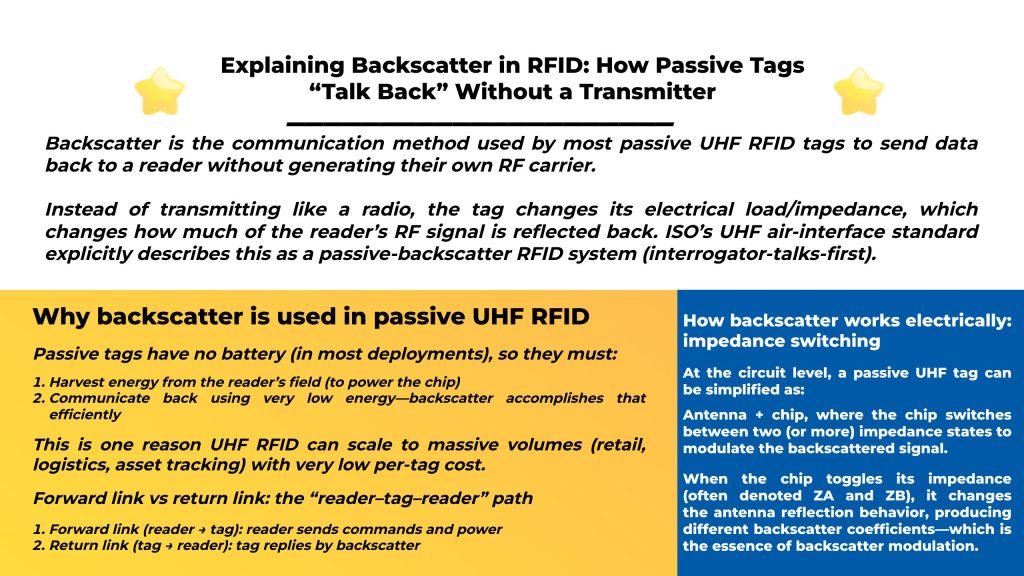
Backscatter is the communication method used by most passive UHF RFID tags to send data back to a reader without generating their own RF carrier.
Instead of transmitting like a radio, the tag changes its electrical load/impedance, which changes how much of the reader’s RF signal is reflected back. ISO’s UHF air-interface standard explicitly describes this as a passive-backscatter RFID system (interrogator-talks-first).
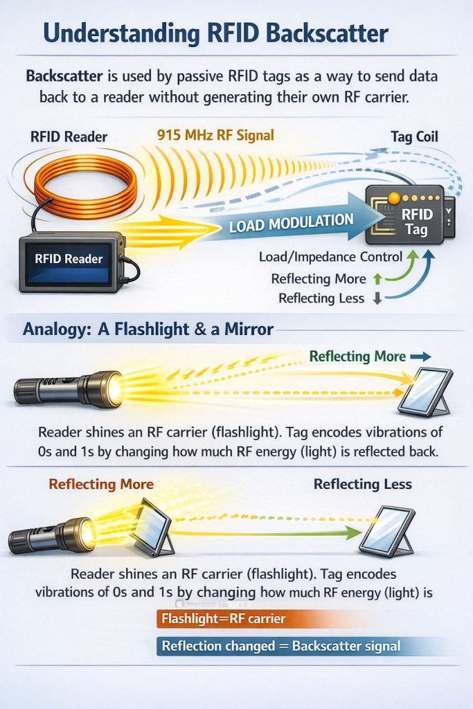
Simple analogy:
A reader shines a flashlight (RF carrier). The tag “blinks” by changing how reflective it is—encoding 0s and 1s in that reflection.
Passive tags have no battery (in most deployments), so they must:
This is one reason UHF RFID can scale to massive volumes (retail, logistics, asset tracking) with very low per-tag cost.
UHF RFID is often described as a reader → tag → reader link:
This two-hop nature matters because range is frequently limited by the return link (the reader must detect a very weak modulated reflection).
At the circuit level, a passive UHF tag can be simplified as:
Antenna + chip, where the chip switches between two (or more) impedance states to modulate the backscattered signal.
When the chip toggles its impedance (often denoted ZA and ZB), it changes the antenna reflection behavior, producing different backscatter coefficients—which is the essence of backscatter modulation.
The tag antenna and chip impedance must be matched well enough to:
Because the tag is reflecting the reader’s carrier, the receiver must detect a small change riding on top of a strong transmitted signal.
Researchers often describe this using concepts like the tag’s radar cross section (RCS) and measurement methods for tag backscatter strength.
In practice, the reader’s RF front-end and DSP must handle:
In RAIN RFID (UHF), the system design guidelines discuss different requirements for the forward link and tag backscatter return link, including return-link data-rate related parameters like BLF (backscatter link frequency).
Key takeaway: Your channel plan, filtering, and reader settings must support both:
(Exact modulation/coding details depend on the Gen2/ISO 18000-63 configuration, but the architectural principle remains: reader talks first; tag replies by backscatter.)
Both approaches involve changing impedance, but the coupling regime differs:
| Item | HF / NFC (13.56 MHz) | UHF RFID (860–960 MHz) |
|---|---|---|
| Coupling | Near-field inductive (coil-to-coil) | Far-field electromagnetic |
| Tag reply method | Load modulation (changes load on coil) | Backscatter (changes reflection coefficient) |
| Typical range | cm-level to short range | meters-level (depends on setup) |
If your project is UHF item tracking, “backscatter” is the core uplink concept.
If the tag antenna is poorly aligned with the reader antenna polarization, return-link signal can drop sharply. UHF RFID antenna and propagation work shows why orientation and channel conditions strongly impact tag performance.
Metal detunes antennas; liquids absorb RF energy. This affects:
Because the return link is weak, reader receiver sensitivity and interference rejection are often decisive—especially in dense RF environments.
Warehouses can create multipath that sometimes helps and sometimes hurts. A “good lab range” can fail in a reflective aisle unless antennas/zones are designed carefully.
UHF systems use anti-collision inventory methods; performance depends on tag density, movement, and reader configuration (session/Q, dwell time, etc.).
They don’t generate their own carrier like an active transmitter. They modulate the reflection of the reader’s carrier.
Writing usually requires more stable power/time at the tag than reading, so write distance is typically shorter and needs tighter zone control (even though it still uses the same backscatter-based uplink for acknowledgments).
If you’re deploying UHF backscatter systems (RAIN / EPC Gen2 / ISO 18000-6C), you’ll usually choose hardware based on:
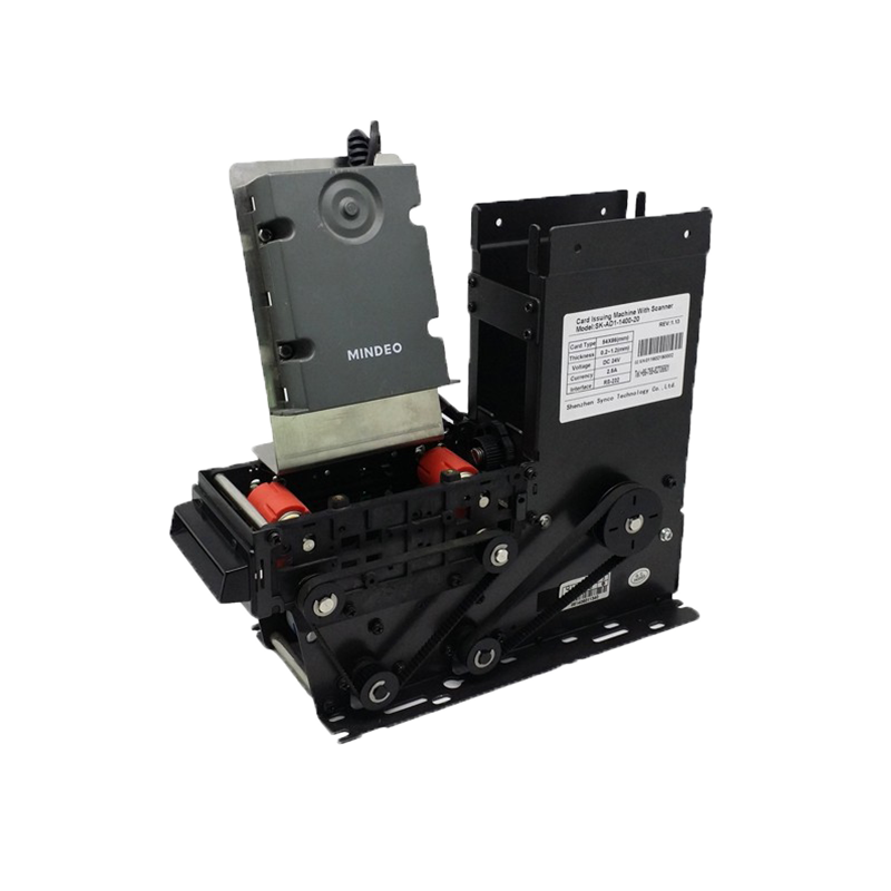
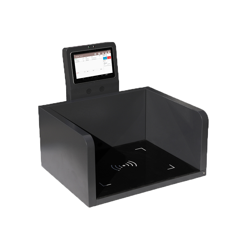
Syncotek’s RFID catalog covers UHF modules, integrated readers, fixed readers, desktop readers, and more.
Example product pages show EPC Gen2 / ISO18000-6C support and development resources (SDK/demo), plus multi-interface options on certain models.
Backscatter is most commonly discussed for UHF passive RFID. HF/NFC usually uses load modulation in the near field, while UHF uses reflection/backscatter in the far field.
Often the return link (reader’s ability to detect a weak backscatter reply), plus tag powering and environmental losses.
Small differences in chip sensitivity, antenna design, matching, and placement on materials can significantly change harvested power and backscatter strength.
Tools are essential assets in many industries. Manufacturing plants, construction companies, hospitals, repair teams, rental businesses, warehouses, and maintenance departments all depend on tools being available, traceable, and properly maintained. However, tool management is often difficult. Tools may be misplaced, borrowed without record, left at job sites, stored in the wrong cabinet, sent for maintenance […]
READ MORE Case Show
Cloud printing is a printing technology based on cloud services, which can be well matched with Internet applications.
READ MORE Industry Info
How to Choose Frequency for Your Access Control System
READ MORE Knowledge
What is a handheld barcode scanner? A handheld barcode scanner (also called a barcode reader) is an optical device that reads printed (or on-screen) barcodes and sends the decoded data to a computer, POS system, mobile device, or industrial controller. Typical scanners include a light source, optics/sensor, and decoder circuitry to interpret the barcode pattern and output the […]
READ MORE Knowledge
What is backscatter (in RFID)? Backscatter is the communication method used by most passive UHF RFID tags to send data back to a reader without generating their own RF carrier. Instead of transmitting like a radio, the tag changes its electrical load/impedance, which changes how much of the reader’s RF signal is reflected back. ISO’s UHF air-interface standard explicitly describes this as a passive-backscatter RFID […]
READ MOREIf you are interested in our services or need customized solutions, please feel free to contact us.