
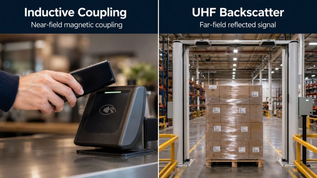
Inductive coupling is the near-field magnetic coupling method used by most LF RFID and HF RFID/NFC systems. In this architecture, the reader generates an alternating magnetic field with a loop antenna, and a nearby tag with its own loop coil captures energy from that field. The tag then uses that harvested energy to power its chip and communicate back to the reader. In RFID engineering, this is the core operating principle behind most 125/134.2 kHz and 13.56 MHz systems.
The easiest way to understand it is to think of the reader coil and the tag coil as a loosely coupled transformer. Energy is transferred through the magnetic field rather than through a long-range radiated RF link. Because the coupling strength drops quickly with distance and orientation mismatch, inductive coupling is naturally suited to short, controlled read zones rather than meter-level bulk reading.
A reader drives current through its antenna coil and creates a magnetic field. When a tag enters that field, the field cuts across the tag coil and induces voltage in it. The tag rectifies that induced voltage, powers its IC, receives reader commands, and then replies by changing its electrical load. That load change is reflected back through the mutual magnetic coupling and detected by the reader. In HF and NFC systems, this tag-to-reader uplink is usually called load modulation.
In practical design terms, inductive coupling is not just about transmitting power. The same antenna system has to support three jobs at once: energizing the tag, sending commands from reader to tag, and recovering the much smaller tag response on the way back. NXP’s ISO/IEC 14443 antenna design documentation describes these three reader-antenna functions directly.
Inductive coupling is the standard operating principle for LF RFID and HF RFID, including NFC. LF commonly refers to around 125 kHz or 134.2 kHz, while HF/NFC is centered at 13.56 MHz. In the HF family, common standards include ISO/IEC 14443 for proximity cards, ISO/IEC 15693 for vicinity-style tags, and ISO/IEC 18092/NFC for phone and smartcard interoperability.
This is different from passive UHF RFID, which typically uses far-field backscatter instead of magnetic coupling. That distinction is one of the most important splits in RFID because it explains why HF/NFC behaves like close-range coil coupling while UHF behaves like a longer-range inventory and portal technology.
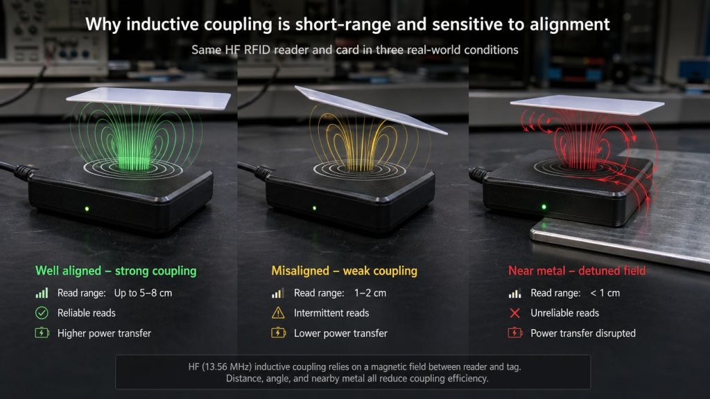
The main limitation is physics. In an inductively coupled system, performance depends on the coupling coefficient between the reader coil and the tag coil, and that coupling falls off quickly as distance increases or alignment gets worse. Research on NFC reader-tag behavior shows that even small spacing or orientation changes can significantly reduce coupling, which hurts both energy harvesting and communication reliability.
That is why HF/NFC systems are usually designed for close, intentional interaction rather than wide-area coverage. A typical ISO/IEC 14443 card tap is around 10 cm or less, while ISO/IEC 15693 can extend to tens of centimeters under optimized conditions. NFC is intentionally even shorter-range for clearer user intent and better user experience.
Inductive coupling depends on loop antennas, not the dipole-style behavior most people associate with UHF. On the tag side, the coil has to capture enough magnetic flux to power the IC. On the reader side, the antenna has to generate a strong and stable magnetic field while still allowing the receiver to detect the tag reply. NXP and Microchip both note that reader and tag performance depend heavily on coil design, resonance, and magnetic coupling efficiency.
Several antenna parameters dominate real performance: coil area, number of turns, Q-factor, resonance frequency, conductor geometry, and the surrounding environment. NXP’s guidance for contactless card and reader coil design specifically highlights coil area, Q-factor, and loaded resonance frequency as major performance parameters, while its reader-frontend documentation notes that conductor thickness, winding spacing, shielding, and nearby metal or ferrite all affect the real antenna values at 13.56 MHz.
An inductively coupled RFID antenna is normally built as a resonant LC circuit. The goal is to tune the antenna around the operating frequency so that the magnetic field is strong enough for efficient power transfer and the receive path can still recover the tag response. Microchip’s 13.56 MHz RFID system guide notes that, for magnetic coupling systems, designers should tune the LC circuit to the carrier frequency, maximize Q appropriately, and make the antenna as large as the application allows.
In real products, tuning cannot be done only on paper. NXP explicitly recommends measuring antenna inductance, resistance, and capacitance under real-life conditions and then performing a tuning procedure, because the actual values shift with PCB type, shielding, winding layout, and nearby materials. That is why HF/NFC designs that work well in a lab can behave differently once they are mounted in a housing, placed near metal, or stacked with other cards or tags.
Inductive coupling and backscatter are both passive communication methods, but they are not the same thing. With inductive coupling, the reader and tag interact mainly through the magnetic field, and the tag replies by load modulation. With UHF backscatter, the reader launches a radiated RF wave and the passive tag replies by changing how it reflects that wave. The first is a near-field coil-coupled system; the second is a far-field radiative system.
This difference explains the usual engineering tradeoff. Inductive coupling is stronger when you want short-range, controlled reads, better tap behavior, and predictable interaction. Backscatter is stronger when you want longer range, broader coverage, and high-speed bulk reading.
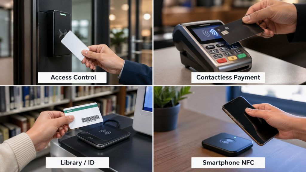
Inductive coupling is widely used in access cards, payment cards, transport ticketing, ID credentials, NFC phone taps, libraries, lab workflows, and other close-range identification tasks. These applications benefit from a controlled read zone, compact loop antennas, and stable short-range behavior. HF/NFC is especially common when interoperability with phones or secure smartcard-style credentials is needed.
LF inductive systems are also used where very short range and robust close-coupled identification are important, while HF/NFC dominates most modern card and phone-centered deployments. In both cases, the reason is the same: inductive coupling provides reliable short-range energy transfer and communication without needing a battery in the tag.
The biggest factors are distance, alignment, coil size, Q-factor, resonance, and environmental detuning. If the tag is rotated poorly relative to the reader field, or if metal and shielding materials disturb the field, coupling strength drops and both power transfer and communication degrade. NFC research and vendor design notes both show that position and orientation strongly affect the coupling coefficient and therefore usable range.
Card stacking and neighboring objects can matter too. NXP’s coil-design guidance notes that loaded resonance frequency and coil Q affect single-card operation, stacked-card behavior, and maximum operating distance. In other words, the best HF/NFC antenna is not just “the biggest coil possible”; it is the coil that is correctly tuned for the intended protocol, card class, and use environment.
It is more accurate to say that inductive coupling usually creates a shorter and more controllable read zone, which can help reduce unintended reads. But short range by itself is not a complete security model. Research on HF RFID security shows that systems based on ISO 14443 and ISO 15693 can still be vulnerable to eavesdropping, skimming, or relay-style attacks if security depends only on proximity and not on protocol-level protections such as authentication and cryptography.
So from an engineering standpoint, inductive coupling improves interaction control, but actual security still depends on the card type, chip features, key management, reader security, and system design.
Choose inductive coupling when the application needs close-range, intentional reads rather than long-range automation. If the workflow looks like tap a card, read a credential, verify an item on a bench, interact with a phone, or identify one tag in a controlled zone, LF or HF/NFC is usually the right family to evaluate.
If the project instead needs portal reads, dock doors, shelf zones, or fast bulk inventory across meters of distance, the better technical fit is usually UHF backscatter rather than inductive coupling. That is why near-field RFID and far-field RFID are best viewed as different tools, not competing labels for the same job.
Inductive coupling is the magnetic near-field operating principle behind most LF RFID, HF RFID, and NFC systems. A loop antenna in the reader creates a magnetic field, a nearby tag coil harvests energy from that field, and the tag replies by load modulation through the same coupled link. Once this principle is clear, many practical RFID behaviors make sense at once: why HF/NFC is short-range, why coil tuning matters, why alignment affects performance, and why these systems are ideal for tap-based and controlled identification workflows.
Inventory management is one of the most important parts of modern business operations. Whether a company manages raw materials, finished goods, returnable containers, tools, retail products, medical supplies, or industrial assets, inventory accuracy directly affects cost, delivery speed, productivity, and customer satisfaction. Traditional inventory methods often rely on manual counting, spreadsheets, or barcode scanning. These […]
READ MORE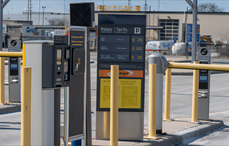 Case Show
Parking System with Syncotek’s Products
READ MORE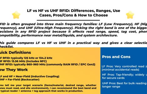 Knowledge
RFID is often grouped into three main frequency families: LF (Low Frequency), HF (High Frequency), and UHF (Ultra-High Frequency). Picking the right band is one of the biggest decisions in any RFID project because it affects read range, speed, tag cost, phone compatibility, performance near metal/liquids, and system architecture. This guide compares LF vs HF vs UHF in a practical way […]
READ MORE Knowledge
What is RFID software? RFID software is the layer that turns RFID hardware signals (readers, antennas, tags, sensors) into usable data and workflows—inventory updates, asset movements, shipping/receiving events, access logs, and analytics. In most real deployments, RFID systems require middleware: software that sits between RFID interrogators (readers) and enterprise applications (WMS/ERP/MES/POS). It manages/configures devices and processes raw tag data by filtering duplicates […]
READ MORE Company Events
The new year is a great opportunity to reflect on your work performance, goals, and challenges, and to make some positive changes that will help you achieve more success and satisfaction.
READ MOREIf you are interested in our services or need customized solutions, please feel free to contact us.