
Load modulation is the uplink method used by most HF RFID and NFC tags to send data back to a reader in the near field. The tag does not generate its own RF carrier. Instead, it changes its electrical load across the tag coil, and that change is coupled back into the reader’s magnetic field so the reader can detect and decode data. This is the basic tag-to-reader communication method in 13.56 MHz systems such as ISO/IEC 14443, ISO/IEC 15693, and NFC.
In engineering terms, HF RFID works more like a loosely coupled transformer than a long-range radio link. The reader coil creates an alternating magnetic field, the tag coil harvests energy from that field to power the chip, and the tag then “wiggles” the field by switching its load. That is why load modulation belongs to near-field inductive coupling, not far-field UHF communication.
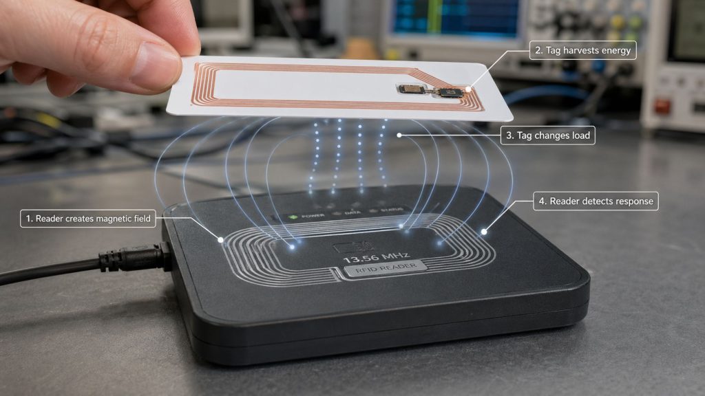
The sequence is straightforward. First, the reader drives a 13.56 MHz carrier into its antenna coil and creates a magnetic field. Second, the tag coil picks up that field and rectifies enough energy to power the IC. Third, the tag changes an internal load, often by switching a resistor, capacitor, or transistor network. That load change slightly changes the current and field conditions seen by the reader, which the reader demodulates as data.
What matters is not large transmitted power from the tag, but a small controlled disturbance imposed on the reader field. In practical reader design, the receiver is trying to detect a very small modulation riding on top of a much stronger carrier generated by the reader itself. That is one reason HF reader analog front ends, filtering, and antenna tuning matter so much.
The word “load” is literal. Inside the tag, the IC changes the effective impedance connected to the antenna coil. When that impedance changes, the magnetic coupling between tag and reader changes slightly as well. The reader sees that change as an amplitude or phase variation that can be decoded into bits. In practice, ICs can create load modulation by switching internal resistive or capacitive elements in and out of circuit.
This is why passive HF tags do not need a battery to reply. The reader supplies the field; the tag only modulates that field. The uplink is therefore extremely power-efficient, but it also depends heavily on coupling strength, alignment, and analog receiver sensitivity.
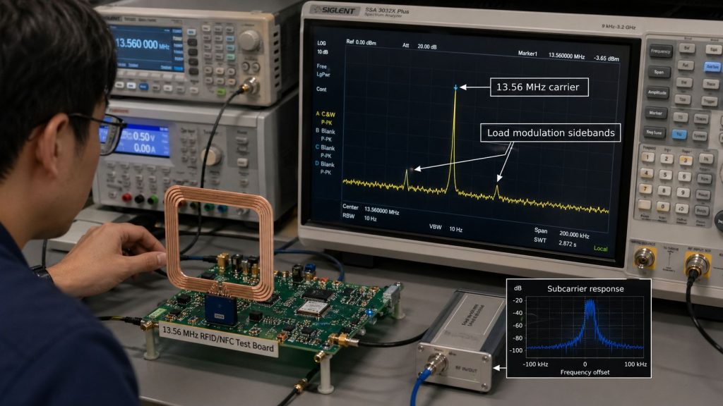
In many HF and NFC systems, the tag response is not detected exactly at the carrier alone. Instead, the load-modulated response creates sidebands around the 13.56 MHz carrier, which makes it easier for the reader to separate the tiny tag response from its own large transmit signal. For ISO/IEC 14443 Type B and NFC-A/NFC-B measurements, a common subcarrier is about 847.5 to 848 kHz, which places sidebands around roughly 12.71 MHz and 14.41 MHz.
From a receiver-design standpoint, this is very important. Modern HF front ends are built to recover these load-modulation sidebands, and some reader ICs explicitly use both sidebands in their receive architecture. This is one reason antenna bandwidth and Q-factor must be balanced: the system needs enough selectivity for efficiency, but still enough bandwidth to pass the modulation sidebands cleanly.
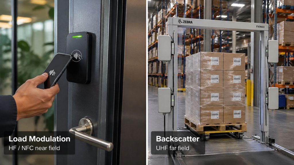
Load modulation and backscatter are related ideas, but they are not the same mechanism. Load modulation is the usual uplink method for LF/HF/NFC near-field systems based on magnetic coupling. Backscatter is the usual uplink method for UHF far-field systems, where the tag changes how it reflects the incident RF wave from the reader. Both allow a passive tag to reply without an active transmitter, but the field physics, antenna behavior, range, and deployment style are different.
A simple engineering shortcut is this: if the system is a short-range coil-to-coil 13.56 MHz design, think load modulation; if it is a UHF portal or long-range inventory design, think backscatter. That rule is not perfect in every special case, but it is correct for the overwhelming majority of RFID deployments.
Load modulation is central to HF RFID at 13.56 MHz. That includes contactless cards and badges, transit tickets, NFC phone interactions, library tags, laboratory and medical workflows, and many secure credential systems. ISO/IEC 14443 is the common “proximity” family used for very short-range card-style interactions, while ISO/IEC 15693 is the “vicinity” family used when longer HF range is useful.
In practical range terms, ISO/IEC 14443 systems are usually designed for tap to around 10 cm, while ISO/IEC 15693 can extend to tens of centimeters and sometimes farther with optimized antennas and favorable conditions. That range difference is one reason both systems use load modulation but serve somewhat different workflows.
If you are designing or selecting HF RFID hardware, understanding load modulation explains several real-world behaviors at once. It explains why HF systems naturally produce a controlled read zone, why coil design matters so much, why alignment between reader coil and tag coil can strongly affect performance, and why HF systems are usually chosen for secure close-range interactions rather than meter-level bulk inventory.
It also explains why HF reader design is a serious analog problem. The reader is transmitting a large carrier while trying to hear a very small reply from a passive tag. Good demodulation depends on antenna tuning, matching, receiver architecture, filtering, noise control, and protocol timing.
Several factors dominate performance. Coil geometry and alignment directly affect magnetic coupling. Resonance tuning and matching at 13.56 MHz affect how efficiently energy is transferred into the tag and how well the reader can recover the response. Q-factor affects both field strength and available bandwidth for sidebands. If Q is too low, energy transfer suffers; if it is too high, the sidebands and data bandwidth can become harder to recover cleanly.
The environment matters too. Nearby metal can detune coils, alter inductance, and reduce coupling efficiency if the antenna was not designed for that condition. Tag size, reader antenna size, spacing, shielding, and enclosure materials all influence actual read distance and stability.
Protocol choice also matters. A system tuned for ISO/IEC 14443 card tapping is not optimized the same way as a system built for ISO/IEC 15693 item or tray reading. Data rate, modulation index, anti-collision behavior, and expected operating distance all influence how the analog front end should be configured.
One common misunderstanding is that the tag is “transmitting like a radio.” In normal passive HF operation, it is not. The tag is changing load on the coupled field; the reader is detecting that disturbance. Another misunderstanding is that load modulation automatically means any 13.56 MHz system will achieve long range. In reality, HF load modulation is fundamentally a near-field method, so range is constrained by magnetic coupling and antenna size.
It is also easy to confuse the terms modulation, load modulation, and active load modulation. In a normal passive tag, the reply is created by changing the load seen by the reader field. In some NFC implementations, active techniques can be used in specific modes, but that is a different design choice from standard passive-card behavior.
For a blog reader evaluating RFID hardware, the practical takeaway is simple. If the workflow is tap, badge, card, ticket, phone interaction, or short-range controlled identification, load-modulated HF/NFC is usually the right family to consider. If the workflow is bulk inventory, portal reads, warehouse automation, or meter-level range, the system usually needs UHF backscatter rather than HF load modulation.
For internal linking on a Syncotek blog, this topic naturally connects to HF RFID, Near-Field Coupling, LF vs HF vs UHF RFID, and Backscatter. Those pages fit the same technical cluster and help users move from principle to product selection.
Load modulation is the tag-to-reader uplink used by most HF RFID and NFC systems. A passive tag harvests energy from the reader’s 13.56 MHz magnetic field, changes its load, and creates a small detectable variation that the reader decodes into data. Once that principle is clear, many practical HF design choices make sense: coil antennas, close-range operation, sideband detection, tuning sensitivity, and the difference between HF/NFC systems and UHF backscatter systems.
 Knowledge
The RFID system auto-identifies vehicles' weight, calculates net weight, and provides real-time monitoring for optimized efficiency.
READ MORE Knowledge
Near-field coupling is the communication method used by LF (125/134 kHz) and HF (13.56 MHz, including NFC) RFID systems. Instead of “radiating” like a long-range radio link, near-field RFID works more like a transformer: a reader coil creates a magnetic field, and the tag coil couples to that field to power up and exchange data. This is why LF/HF/NFC are typically short-range, […]
READ MORE Knowledge
The RFID system auto-identifies vehicles' weight, calculates net weight, and provides real-time monitoring for optimized efficiency.
READ MORE Knowledge
HF RFID runs at 13.56 MHz and is widely used for access control badges, contactless payments, libraries, healthcare wristbands, and NFC phone tap experiences. When people say “HF RFID,” they often mean very different things—because HF is a frequency band, while standards define the protocol stack (how tags and readers actually communicate). More about HF […]
READ MORE Knowledge
Active RFID is a type of radio frequency identification technology that uses battery-powered tags to transmit data to RFID readers. Because the tag has its own power source, it can send signals over a much longer distance than a passive RFID tag, which relies on the reader’s signal for energy. That is why Active RFID is commonly […]
READ MOREIf you are interested in our services or need customized solutions, please feel free to contact us.