
Load modulation is the method most HF RFID (13.56 MHz) and NFC tags use to send data back to a reader in the near field. Instead of actively transmitting RF power, the tag switches an electrical load (often a resistor or transistor network) across its antenna coil. That change in tag current is coupled back through mutual inductance and becomes a small, detectable variation on the reader side.
In plain terms:
At HF (13.56 MHz), communication is largely based on magnetic (inductive) coupling between two coils. The reader powers the passive tag, and the tag’s load changes create a measurable effect back at the reader.
Related read: https://syncotek.com/near-field-coupling/
In UHF RFID, the tag-reader link is commonly described as backscatter modulation: the tag changes its impedance state to alter the reflected signal (the “reverse channel”), and range is strongly influenced by reverse-link path loss.
Realted Read:
Quick mental model:
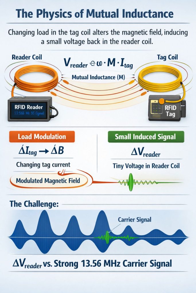
Two coils near each other have mutual inductance (M). When the tag changes its load, the tag coil current changes. That changes the magnetic field, which induces a small voltage/current change back at the reader coil. Mutual inductance is the core physical principle behind inductively-coupled RFID.
A common implementation is exactly what many standards-oriented descriptions say: a modulation resistor (or equivalent load network) is connected in parallel to the tag antenna and switched on/off according to the data stream.
In ISO/IEC 14443 proximity card systems, tag-to-reader uplink uses a subcarrier around ~847.5–848 kHz. The reader can then filter around that subcarrier region (sidebands around 13.56 MHz) to extract the tag data more reliably.
One practical write-up notes that ISO/IEC 14443 Type A specifies load modulation using a subcarrier (≈848 kHz), and that subcarrier is then ASK-modulated with coding (e.g., Manchester) for the uplink.
A simple way to express the coupling idea is:
The key engineering challenge is that ΔV_reader is tiny compared with the reader’s own strong 13.56 MHz carrier.
When the tag load-modulates using a subcarrier, the reader doesn’t look for a big amplitude change at 13.56 MHz. Instead, it looks for sidebands at:
13.56 MHz ± f_subcarrier (and sometimes higher-order products)
This is why HF/NFC reader ICs emphasize receiver architectures for subcarrier load modulation and, in some designs, using both sidebands via differential receiving concepts.
“Classic” passive load modulation depends purely on how strongly the coils are coupled. Some modern NFC front-ends support active load modulation modes (especially for card emulation / PICC behaviors) to improve the uplink robustness and range in certain scenarios. For example, NXP’s PN5190B1 highlights PICC mode with active load modulation up to 848 kbit/s.
A detailed discussion dedicated to active load modulation for contactless systems is also published by Finkenzeller and collaborators (commonly referenced in contactless literature).
Because the link is inductive, small geometry changes can significantly affect the uplink SNR.
A high-Q resonant coil boosts field strength and sensitivity but can reduce bandwidth and make the system more sensitive to detuning (metal nearby, hand effects, coil tolerances). HF/NFC design references frequently discuss the importance of resonance and coupling in practical systems.
The reader must detect a very small modulated signal riding on top of its own transmitted carrier. Reader ICs therefore emphasize robust demodulation/decoding of ISO/IEC 14443-compatible tag signals.
Because the uplink appears in a specific spectral region (around the subcarrier sidebands), filter design and EMI matter a lot—especially in noisy environments (switch-mode supplies, nearby RF sources).
ISO/IEC 14443 Type A/B systems commonly operate with data rates from 106 kbit/s up to 848 kbit/s, and the uplink design must handle those modes.
Reading is mostly about stable coupling and a clean uplink demodulation path. The reader is continuously powering the tag while listening for the load-modulated response.
Writing generally requires:
HF/NFC reader ICs are typically built as reader/writer front-ends specifically for ISO/IEC 14443 A/B communication at 13.56 MHz.
Reeled Read: RFID Read and Write: How RFID Data Is Read, Written, Locked, and Verified in Real Deployments
Not in the classic sense. A passive tag is not generating RF power like a transmitter; it is changing its load, which the reader detects through coupling.
They are related (both involve changing impedance/loading), but they are typically discussed in different coupling regimes:
Most commonly in HF RFID / NFC at 13.56 MHz, especially ISO/IEC 14443 proximity systems where tag-to-reader uses subcarrier-based load modulation.
Using a subcarrier places the tag response into sidebands that are easier for the reader to filter and demodulate from the large carrier field.
A mode where the tag/card-side behavior strengthens or shapes the uplink beyond purely passive loading effects; some modern NFC front-ends explicitly support active load modulation in card mode.
 Knowledge
The RFID system auto-identifies vehicles' weight, calculates net weight, and provides real-time monitoring for optimized efficiency.
READ MORE Knowledge
What is an RFID chip? An RFID chip is a small integrated circuit (IC) used in radio-frequency identification systems to store an identifier and/or data and communicate wirelessly with an RFID reader. In everyday conversations, “RFID chip” can mean two different things: RFID tag chip (Tag IC / transponder IC) – the chip inside a […]
READ MORE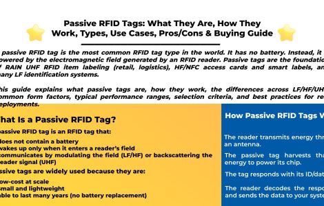 Knowledge
A passive RFID tag is the most common RFID tag type in the world. It has no battery. Instead, it is powered by the electromagnetic field generated by an RFID reader. Passive tags are the foundation of RAIN UHF RFID item labeling (retail, logistics), HF/NFC access cards and smart labels, and many LF identification systems. This guide explains what passive tags are, how they work, the differences […]
READ MORE Knowledge
RFID tags are small devices (a chip + antenna) that store an ID (and sometimes more data) and communicate wirelessly with an RFID reader. They’re used to identify, track, and manage items in warehousing, retail, manufacturing (WIP), healthcare, asset tracking, access control, and logistics—often faster and with less manual work than barcodes. This guide explains […]
READ MORE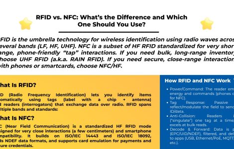 Knowledge
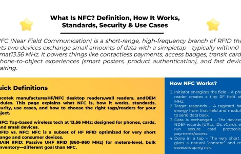
Learn the real differences between RFID and NFC—frequencies, range, security, smartphone compatibility, data models, and use cases. See when to choose UHF RFID (RAIN) vs. NFC, and how Syncotek readers fit your project.
READ MOREIf you are interested in our services or need customized solutions, please feel free to contact us.